background image

Network Wiring (MX-5000 Series)

2 - 30 •  •  •   MPS-4100 product guide

1. Wire power, alarm, tamper and self-test pairs to TB1 (see Figure 2-22). 

Observe polarity

.

2. Wire audio to the Slave audio terminals on TB3.

Do not use the TB1 audio terminals for a Slave Receiver.

3. Wire power and tamper for the Slave Transmitter to TB2. The Transmitter 

tamper output must be set to NC.

If the Transmitter tamper will not be wired to the Receiver, a 

jumper must be placed across TB2-3 & TB2-4.

4. Set the Receiver modulation frequency to match the Transmitter modulation 

frequency via JP1 and JP2.

5. Configure the operating parameters via S1 and S2. See Table 2-4.

A shielded pair cable for the audio between the Slave and Host 

Receivers is recommended. The shield should be tied to any 

Common terminal on TB3 of the Host Receiver only.

Содержание MPS-4100

Страница 1: ...Product MPS 4100 Microwave Protection System Guide E6DA0102 003 Rev C Third Edition April 27 2009 ...

Страница 2: ...void the user s authority to operate the equipment Senstar s Quality Management System is IS0 9001 2000 registered Compliance USA FCC Certification This device complies with part 15 of the FCC Rules Operation is subject to the following two conditions 1 This device may not cause harmful interference and 2 this device must accept any interference received including interference that may cause undes...

Страница 3: ...smitter 1 5 MPS 4100 Receiver 1 6 Coverage pattern 1 6 2 Installation Installation planning 2 1 Positioning the MPS 4100 2 1 Terrain 2 2 Microwave signal considerations 2 3 Physical protection 2 3 Optimum security 2 3 Wiring and configuration 2 4 MPS 4100 configuration options 2 5 Transmitter S1 tamper 2 5 Transmitter jumper 2 5 Receiver S1 2 5 Receiver S2 2 6 Receiver jumpers 2 6 DIP switch illus...

Страница 4: ... network device address 2 20 Setting the baud rate 2 20 Connecting the network wiring 2 21 Mounting the Communications Interface Card 2 22 Labelling 2 22 Setting up the MPS 4100 Receiver card 2 23 Wiring the Receiver for Silver StarNeT 1000 2 24 Single Zone 2 24 Dual Zone Host Slave configuration 2 24 Host or Slave Transmitter 2 25 Host Receiver 2 25 Slave Receiver 2 26 Network Wiring MX 5000 Seri...

Страница 5: ...ection a 6 Low security applications a 6 Rules for areas with significant snow accumulation a 6 Post mounting and grounding a 7 Stacking bistatic microwaves a 8 a 8 Introduction a 8 Good practice a 8 Determining the mounting height a 9 Mounting height procedure a 10 Heavy snow areas a 11 Advantages of microwave stacking a 12 Disadvantages of microwave stacking a 12 Conclusion a 12 b StarNeT 1000 C...

Страница 6: ......

Страница 7: ...consists of one Transmitter Tx unit and one Receiver Rx unit The Transmitter is a Dielectric Resonant Oscillator DRO designed to radiate microwave power at 10 525 GHz This oscillator is pulse modulated on off switched at a 50 duty cycle with a selectable frequency of 3 4 5 7 5 10 5 18 or 27 kHz The transmitted energy is received and processed by the Receiver using Phase Locked Loop PLL technology ...

Страница 8: ...owave field is established by the Planar Linear Array Antenna elements housed within the Transmitter and Receiver The maximum range is 183 m 600 feet The pattern width is proportional to the distance between the Transmitter and Receiver see Figure 1 4 Figure 1 2 MPS 4100 microwave unit ...

Страница 9: ...nt level regardless of the Transmitter Receiver separation distance maximum TX RX separation distance 183 m 600 feet The amplifier output is applied to a phase locked loop PLL detector which operates as a narrow bandpass filter at the selected modulation frequency The Receiver s modulation frequency is selected to match the modulation frequency of the Transmitter while rejecting spurious signals a...

Страница 10: ...hich establishes the strongest possible signal is facilitated by a built in alignment aid A series of LED s on the Receiver circuit board indicate when optimum alignment and maximum signal strength have been achieved A 600 ohm impedance audio jack and voltage test points are also provided on the Receiver card to enable headphones or a voltmeter to be used as alignment aids Audio output The MPS 410...

Страница 11: ...rd includes the modulator circuit to drive the oscillator One of six modulation frequencies can be selected via jumpers located on the board The Transmitter includes a Tamper switch with selectable NO NC output that signals when the cover on the rear of the housing has been removed The Tamper switch is a 2 position plunger secure alarm and includes a pull out position that disables tamper notifica...

Страница 12: ...he Receiver circuit board includes three LED s for indicating Alarm Wrong Channel and Jam conditions The Alarm LED indicates an alarm condition The Wrong Channel LED indicates that the modulation frequency of the Receiver does not match that of the Transmitter The Jam LED indicates that the Receiver is picking up two microwave signals at the same modulation frequency signifying interference betwee...

Страница 13: ...Transmitter and Receiver The energy field development is not immediate resulting in a dead zone in front of the Transmitter and Receiver in which it is possible to crawl under the pattern undetected For this reason it is necessary to overlap or offset Transmitters and Receivers to cover this dead zone Receivers and Transmitters should be offset at least 4 5 m 15 ft at corners and 9 m 30 ft at midp...

Страница 14: ... complete coverage around a corner on a protected perimeter Figure 1 6 illustrates an intermediate offset which is used to extend the length of a straight microwave coverage pattern by using two microwave pairs Figure 1 5 Dead zone overlap protection side view Figure 1 6 Intermediate overlap top view corner overlap 4 5 m 15 ft 4 5 m 15 ft full coverage along dotted lines 4 5 m 15 ft dead zone no c...

Страница 15: ...maximum separation distance between the Receiver and Transmitter is 183 m 600 ft However for high security applications the recommended maximum separation distance is 100 m 328 ft The maximum width of the zone is determined by the amount of open space to the left and right of the center line between the Transmitter and Receiver The area to be protected must be free of obstructions and moving objec...

Страница 16: ...cm 6 in see Figure 2 2 The protected area s surface can be any stable reasonably smooth material such as concrete asphalt soil or gravel If there is grass or vegetation in the protected area it must be kept cut to a maximum of 8 cm 3 in in height An MPS 4100 should not be operated over open water or where standing puddles will form For environments in which snow accumulates during the winter month...

Страница 17: ...smitter and Receiver in a location which provides protection from both accidental damage and tampering If microwave units are being installed near roadways or where they are vulnerable to vehicle traffic install protective devices such as bumper posts or parking guards Optimum security Choose a location that will provide optimum security yet be free from nuisance alarms Always locate the MPS 4100 ...

Страница 18: ...ovides dry relay outputs for alarm and tamper that can be wired to virtually any alarm sensor with auxiliary inputs including the OmniTrax processor XField processor Perimitrax Sensor Module Intelli FLEX processor PLC transponder etc The MPS 4100 can report alarm data via the Silver Network to the SentientTM security management system or to a Perimitrax or Intelli FLEX Central Controller Senstar 1...

Страница 19: ...s The following is a summary of the configuration options for the MPS 4100 via jumpers and DIP switches Transmitter S1 tamper S1 1 ON selects NO tamper output OFF disables NO output S1 2 ON selects NC tamper output OFF disables NC output S1 3 ON bypasses the 3 kΩ end of line resistor EOLR OFF adds the 3 kΩ EOLR in series with the NC output S1 4 ON enables unswitched power to Transmitter OFF enable...

Страница 20: ...quency Channels 1 through 6 JP3 Sets tamper output to either Normally Open or Normally Closed JP4 Sets the optional 3 kΩ end of line supervision for tamper NC output JP5 Sets the alarm output to either Normally Open or Normally Closed JP6 Sets the optional 3 kΩ end of line supervision for alarm NC output JP7 Sets the Receiver s response to signal disruption to FAST or SLOW DIP switch illustration ...

Страница 21: ...sts should be 8 9 or 10 cm 3 3 or 4 inch O D pipe 1 2 m 4 ft high and fixed in a concrete footing The wire size for power cables should be sufficient to minimize the voltage drop between the power supply and the units Refer to Table 2 1 for recommended wire sizes based on the load requirements and the length of each wire run Figure 2 5 Post mounting Post mount bracket post side Post mount bracket ...

Страница 22: ...of the MPS 4100 see Figure 2 6 3 Remove the cover by loosening the 4 captive screws Pull the cover away and allow it to hang by the strain relief 4 Attach 2 cm in diameter watertight flex conduit between the junction box at the base of the post and the conduit connector on the rear cover of the microwave unit Be sure the conduit outlet on the back of the unit faces down to allow water to drain awa...

Страница 23: ...microwave unit installation enclosure bottom hex nut with tooth washer flat washer ground screw ground lug hex nut with tooth washer the top of the post can be cut off and capped after final alignment ground rod ground wire MPS 4100 unit mounting bracket 8 9 or 10 cm 3 3 5 or 4 in O D mounting post minimum 1 2 m 4 ft above ground concrete base min 91 cm 3 ft below ground OR min 15 cm 6 in below fr...

Страница 24: ...The Transmitter modulation frequency must match the Receiver modulation frequency 3 Configure the Tamper notification for conventional relay output or switched power see Figure 2 8 Figure 2 7 MPS 4100 Transmitter connections To Receiver TB2 OR Alarm annunciator 12 to 24 VDC from Receiver TB2 OR power supply Transmitter tamper configuration Modulation frequency selection jumpers MUST match Receiver...

Страница 25: ...he tamper switch Opening the cover interrupts the input voltage and shuts off the transmission of microwave energy resulting in an alarm condition at the receiver This option can be used when it is impractical or undesirable to run wiring for the tamper output Relay output tamper Switched power tamper Use SW 1 SW 2 and SW 3 to configure Relay Output Tamper notification SW 4 is always ON SW 5 and S...

Страница 26: ...ust be set to NC 3 Configure the alarm and tamper relay outputs via jumpers JP3 JP4 JP5 and JP6 see Table 2 2 Figure 2 9 MPS 4100 Receiver connections for relay output Audio O P self test I P 12 VDC sensor alarm O P Tamper O P from Transmitter tape shield 12 to 24 VDC O P to Transmitter 12 to 24 VDC I P from power supply tamper alarm O P XMTTR CONNECT TMPR PWR COM ALM 2 TMPR TEST 2 COM AUD 2 TB3 A...

Страница 27: ...eceiver details Alarm Relay Tamper Relay For N C place a shunt on JP5 pins 1 and 2 For N O place a shunt on JP5 pins 2 and 3 For N C 3 K Ohm supervision place a shunt on JP6 pins 2 and 3 For N C place a shunt on JP3 pins 1 and 2 For N O place a shunt on JP3 pins 2 and 3 For N C 3 K Ohm supervision place a shunt on JP4 pins 2 and 3 Table 2 2 Alarm and tamper relay configuration Figure 2 10 MPS 4100...

Страница 28: ...ed signal strength 0 to 5 V range 3 5 V OK JP3 Receiver tamper relay setting NO normally open NC normally closed Local Audio 1 8 in headphone jack audio assessment of microwave field disturbance JP4 Tamper relay supervision selection 3K on board 3 kΩ series EOL supervision requires NC setting on JP3 NO 3K no supervision resistor S1 Receiver configuration DIP switch see Table 2 4 for details JP5 Re...

Страница 29: ... JP7 target speed settings DIP switch S1 Function DIP switch S2 Function S1 1 ON for network operation OFF for relay output standard mode S2 1 ON enables audio O P via TB3 OFF enables audio O P via TB1 S1 2 ON enables self test standard mode OFF for network operation S2 2 Not used S1 3 ON for network operation OFF for relay output standard mode S2 3 ON connects Tamper to network O P OFF for standa...

Страница 30: ...nment for reduced power consumption Alarm Relay Reset Enables reset of alarm relay In OFF position alarm relay latches following alarm until reset manually Toggle S2 5 to reset alarm relay Alarm Relay Enable Enables alarm relay operation for relay output version May be turned OFF for network operation if local alarm annunciation is not required Figure 2 12 MPS 4100 Receiver configuration options 5...

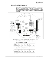
Страница 31: ... Card E6BA01__ ___ REV __ POWER TX A RX A FAULT A RESERVE TX B RX B FAULT B ALARM 1 ALARM 2 SUPERVISION 1 SUPERVISON 2 AUDIO SEL 2 AUDIO SEL 1 SELF TEST 1 SELF TEST 2 S2 ON ON J2 TB2 TB1 J1 S1 polarizing plug pin 8 status LEDs J2 transponder connect connect to P1 on Receiver TB2 A side EIA 422 connection TB1 B side EIA 422 connection J1 firmware update S1 sw1 to sw7 address select sw8 network type...

Страница 32: ...wave unit to TB3 lightning suppression devices for communication circuits on board microprocessor conformal coated PCB 16 diagnostic status LEDs Software setup For StarNeT 1000 systems configure the MPS 4100 Microwave System in the StarNeT site database as a PLC 430 IWAVE Transponder by following the directions in the SIMPL Site Creation Guide J4DA0202 and the Control Program Maintenance Guide J4D...

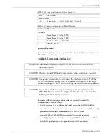
Страница 33: ...p to the ground screw on the enclosure MPS 4100 input point mapping Silver Network Point Description Sensor Alarms 1 2 Microwave 1 2 bit 0 Alarm bit 1 Tamper MPS 4100 output point mapping Silver Network Point Description Controls 1 Audio Select 1 Audio 2 LED 2 Audio Select 2 Audio 1 LED 3 Self Test 1 2 Self Test LED 1 4 Self Test LED 2 WARNING Disconnect the power source to the MPS 4100 microwave ...

Страница 34: ...ed devices communicate at a fixed baud rate of 57 6 k the Silver Network baud rate cannot be adjusted Figure 2 14 Network device address settings Figure 2 15 Baud rate settings SW1 device address Silver 1 32 StarNeT 0 127 network type OFF Silver ON StarNeT address 1 2 3 4 5 6 7 0 1 2 3 4 l 8 l 16 l 32 l 64 l 126 127 OFF OFF OFF OFF OFF OFF OFF ON OFF OFF OFF OFF OFF OFF OFF ON OFF OFF OFF OFF OFF ...

Страница 35: ... other end 6 Plug the B side terminal block into TB1 7 Plug the A side terminal block into TB2 8 For multi mode fiber optic cable make the wiring connections according to Figure 2 16 Figure 2 16 Network communication wiring connections multi mode fiber optic EIA 422 copper EIA 422 copper fiber optic Connections to next device RXB TXB TXA RXA Use single point grounding connect only one side of shie...

Страница 36: ... SW ALARM JAM WRONG CHANNEL ALIGNMENT AID LEDs CH6 CH5 CH4 CH3 CH2 CH1 LOCAL AUDIO sensitivity JP7 3K no 3K NC NO NC NO FAST SLOW POOR BETTER BEST TAMPER ALARM TP6 TP5 TAMPER RV3 1 2 3 4 5 6 ON OFF 1 2 3 4 5 6 ON OFF RV2 3K no 3K alarm duration RV1 TP12 LD12 LD1 LD13 LD11 LD2 MPS 4100 Microwave Receiver COM ALM 2 TMPR TEST 2 COM AUD 2 TB3 AUD PWR DATA TEST TMP ALM TB1 XMTTR CONNECT TMPR PWR TB2 P1...

Страница 37: ...tem SWITCH 1 2 3 4 5 6 POSITION ON OFF ON OFF ON ON SWITCH 1 2 3 4 5 6 POSITION OFF OFF ON ON ON OFF install terminal block and 3 k resistors on TB3 for single systems and on Slave Receivers setup alarm tamper relays as NC 3k Ohm supervision JP3 JP4 JP5 JP6 install MPS 4100 Communications Interface Card on P1 set DIP switches S1 and S2 switch ON 1 S1 S2 JP4 JP6 JP5 JP3 JP1 JP2 S3 TAMPER SW Slave c...

Страница 38: ...nsmitter tamper reporting option no tamper wiring Figure 2 20 Master Slave connection diagram CH6 CH5 CH4 CH3 CH2 CH1 JP1 S1 ON 6 5 1 2 4 3 OFF TMPR PWR TB1 MPS 4100 Microwave Transmitter SLAVE PWR LED CH6 CH5 CH4 CH3 CH2 CH1 JP1 S1 ON 6 5 1 2 4 3 OFF TMPR PWR TB1 PWR LED MPS 4100 Microwave Transmitter HOST XMTTR CONNECT TMPR PWR COM ALM 2 TMPR TEST 2 COM AUD 2 TB3 AUD PWR DATA TEST TMP ALM TB1 CH...

Страница 39: ...e Transmitter must be NC 3 Install the terminal block and 3 k resistors included in kit E6KT0200 on TB3 Figure 2 21 MPS 4100 Host Receiver connections Audio O P Tamper O P from Transmitter tape shield 12 to 24 VDC O P to Transmitter and Slave Receiver 12 to 24 VDC I P from power supply network connection via MPS 4100 Communication Interface Card on PI Alarm I P from Slave Receiver Tamper I P from ...

Страница 40: ...ee Figure 2 10 The 3 kΩ EOL resistor for the tamper circuit must be set at the Slave Transmitter If the Transmitter tamper is not being connected to the Receiver a jumper must be placed across pins 3 4 on TB2 Figure 2 22 MPS 4100 Slave Receiver connections Audio O P to Host Receiver self test I P 12 VDC sensor alarm O P to Host Receiver tamper O P from Transmitter tape shield 12 to 24 VDC O P to T...

Страница 41: ...rminal on TB3 of the Host Receiver Trim back and tape the shield at the Slave Receiver 2 Wire audio to the Slave audio terminals on TB3 Do not use the TB1 audio terminals for a Slave Receiver 3 Wire power and tamper for the Slave Transmitter to TB2 Transmitter tamper output must be set to NC 4 Set the Receiver modulation frequency to match the Transmitter modulation frequency via JP1 and JP2 5 Con...

Страница 42: ...ver the Slave Transmitter wires to the Slave Receiver Host Receiver 1 Connect the audio power and data pairs from the shielded interconnect cable to TB1 see Figure 2 23 See the note below regarding shield terminations Observe Polarity All shields should be clipped and taped off including the overall shield Incoming and outgoing cable shields should be connected and taped off DO NOT ALLOW THE INDIV...

Страница 43: ...Relay outputs for alarm and tamper must be set for NC 3 kΩ supervised via jumpers JP3 JP4 JP5 and JP6 see Figure 2 10 The 3 kΩ EOLR for the tamper circuit should be set at the Slave Transmitter The return wires for alarm tamper audio and self test may be commoned together Figure 2 23 MPS 4100 Host Receiver connections TB1 TB2 TB3 S2 AUD PWR DATA TEST TMP ALM XMTTR CONNECT TMPR PWR COM ALM 2 TMPR T...

Страница 44: ...er to TB2 The Transmitter tamper output must be set to NC If the Transmitter tamper will not be wired to the Receiver a jumper must be placed across TB2 3 TB2 4 4 Set the Receiver modulation frequency to match the Transmitter modulation frequency via JP1 and JP2 5 Configure the operating parameters via S1 and S2 See Table 2 4 A shielded pair cable for the audio between the Slave and Host Receivers...

Страница 45: ...at The power LED illuminates on the Transmitter Several LED s illuminate on the Receiver to verify initial operation of the system Network version Silver Network StarNeT 1000 Apply power to the MPS 4100 Observe that LED 1 on the Communication Interface Card illuminates If the alarm display and control System is configured to poll the MPS 4100 System the Rec A Rec B and Xmit LEDs will flash intermi...

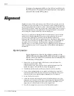
Страница 46: ...fall an unstable zone For environments where there is significant snow accumulation refer to application notes 1 and 2 in Appendix a for installation and alignment information Alignment procedure Proper alignment is critical to the reliable operation of the MPS 4100 A poorly aligned MPS 4100 can result in nuisance alarms which can reduce the confidence level and thereby the effectiveness of the sy...

Страница 47: ...alignment procedure may differ from the standard procedures In this type of environment a hard paved surface is recommended for the microwave zone to facilitate snow removal Refer to Do s and Don ts a planning primer and Stacking bistatic microwaves for information about installing and aligning the MPS 4100 Microwave system in environments with significant snow accumulation Final testing and adjus...

Страница 48: ...ria 5 Consult the project specifications for additional detection tests and perform as required Silver Network Test Refer to the product documentation for the alarm display and control system to test MPS 4100 units that communicate over the Silver Network StarNeT 1000 Test Refer to the Control Program Maintenance Guide J4DA0402 and the Control Program Operator s Guide J4DA0302 for StarNeT 1000 tes...

Страница 49: ...embly of the Transmitter and Receiver as follows 1 Remove the rear cover of the Transmitter 2 Loosen the 4 screws that hold the PCB assembly to the chassis 3 Rotate the assembly 90º clockwise until the Wide Beam mark points down 4 Tighten the 4 screws to secure the assembly to the chassis 5 Repeat the process at the Receiver The Receiver board is not labelled for Narrow Beam and Wide Beam When in ...

Страница 50: ...verifying its operation 5 Occasionally one of the microwave units can be accidentally knocked out of alignment Verify the alignment of the microwave system refer to the Alignment section Realign the system as required 6 Increase the sensitivity at RV1 to the maximum setting turn fully clockwise and retest the microwave detection If the microwave does NOT detect a valid target obtain an RMA number ...

Страница 51: ...il you achieve an acceptable level of detection without an unacceptable false alarm rate Silver Network StarNeT 1000 Communication Interface Card The Communication Interface Card includes 12 diagnostic status LEDs to assist troubleshooting Test the MPS 4100 according to the directions in the alarm display and control system Using a two way radio for communication have a technician monitor the LEDs...

Страница 52: ... flexible weather proof conduit fitting for power and alarm cables Weather proofing Aluminum enclosure powder coated All openings gasketed and sealed Conformal coated circuit boards Lightning protection Input Output lines protected by gas discharge arrestors and Transorbs 90 volts 5000 amperes Operating temperature 40ºC to 70ºC 40ºF to 158ºF Alarm output Isolated and supervised relay contacts jump...

Страница 53: ... band toward a receiver The receiver picks up an electromagnetic signal composed of both the direct signal from the transmitter and the reflected signal from the ground and other nearby objects Any metallic or water containing living conductive object moving within the microwave field alters the received signal in amplitude and phase The changes in the received signal are analyzed and if they meet...

Страница 54: ...e a 4 Top view intermediate overlap Beam centerline small detection area large detection area small detection area 76 cm 30 in to antenna center 4 5 m 15 ft offset microwave unit provides coverage of the area below the transmitter receiver corner overlap 4 5 m 15 ft 4 5 m 15 ft top view beam centerline beam centerline intermediate overlap 9 m 30 ft offset 46 to 51 cm 18 to 20 in ...

Страница 55: ...ation between the transmitter and receiver must not exceed 100 m 328 ft This is referred to as a high security microwave detection zone At the maximum separation distance for bistatic microwave units only upright walking intruders are reliably detected Microwave detection is NOT terrain following Only line of sight detection is provided by bistatic microwaves Unit separation and the mid point zone...

Страница 56: ...fences that are 6 m apart the maximum zone length is calculated by dividing 3 m distance from beam centerline to fence by 0 066 MPS 4100 numeric factor which equals 45 m Figure a 6 illustrates a typical MPS 4100 zone length detection pattern at 91 m and the zone length adjustment that must be made for the same system if it is installed between parallel fences that are 6 m apart It is possible to i...

Страница 57: ...f potential problems with animal initiated nuisance alarms Do limit the length of the microwave zone to exclude fences buildings and other reflective surfaces from inside the detection area Use additional overlapping and offset microwave units to provide complete coverage of the area Don t allow fences buildings or other reflective objects into the microwave zone or nuisance alarms and inconsisten...

Страница 58: ...round covers are acceptable well mown grass 7 6 cm 3 in or less asphalt concrete or hard packed soil Rules for areas with significant snow accumulation The accumulation of snow in the detection zone between the transmitter and receiver reduces their effective mounting height The reduction in mounting height changes the ground reflection characteristic which greatly affects the received signal leve...

Страница 59: ...ions Post mounting and grounding Each transmitter and receiver is mounted on a 7 6 to 10 cm 3 to 4 in steel post depending on the hardware supplied Each post is installed in a concrete base that is at least 61 cm 24 in in diameter and 91 cm 36 in deep OR 15 cm 6 in below the frost line whichever is greater The microwave units must be securely fixed and must not move when the wind blows or when the...

Страница 60: ...lowing steps MUST be taken in order to stack two microwave sensors 1 Ensure that the two pairs have DIFFERENT modulation frequencies 2 Ensure that the two pairs have DIFFERENT antenna polarizations for the microwave signal This will help prevent interference between the two sets of microwave units Order one pair with the antenna elements rotated 90º or for the MPS 4100 rotate both antennas 90º pri...

Страница 61: ...eceived signal is greatly influenced by the mid point reflections The phase relationship between the direct and reflected signals will slowly change as the sensor antennas are raised from the ground level The two signals direct and reflected will combine constructively in phase or destructively out of phase depending on the sensor mounting height and separation distance Constructive phasing is pre...

Страница 62: ...t the operating point is below N1 see Figure a 10 or Figure a 11 3 For an installation where both X Band and K Band microwave units are being employed the K Band Microwave Series 24000 unit MUST be the lower unit K Band microwave sensors have better sensitivity to slow moving intruders However they are more susceptible to nuisance alarms from rain and snow The closely spaced nodal lines see Figure...

Страница 63: ...ulates the effective mounting height will decrease and the operating point will shift toward an area of constructive phasing Figure a 10 X band sensor MPS 4100 Series 14000 Series 16000 Figure a 11 K band sensor Series 24000 140 INCHES CM 120 100 360 330 300 270 80 240 210 180 60 40 150 120 90 60 30 0 20 0 0 15 30 45 60 75 90 100 200 300 METERS FEET 105 120 135 150 165 180 400 500 600 700 800 195 ...

Страница 64: ...larms caused by rain and snow there is a greater potential for interference between microwave pairs because the upper unit is so high above the ground its operating characteristics received signal can change from constructive phasing strong received signal to destructive phasing weak or no received signal with a slight change in mounting height Although the mounting height is optimized during inst...

Страница 65: ...S 4100 Microwave system to communicate on the StarNeT 1000 network Installed directly on the MPS 4100 Receiver unit PCB the card provides redundant network communications through two removable terminal blocks Figure b 1 Communication Interface Card J2 XPNDR CONNECT Ground strap SW2 Network device address SW1 Baud rate and LED PWR J1 B side network communications J3 A side network communications di...

Страница 66: ...croprocessor conformal coated PCB 12 diagnostic status LEDs Software setup Before installing the Communications Interface Card configure the MPS 4100 Microwave System in the StarNeT site database as a PLC 430 IWAVE Transponder by following the directions in the SIMPL Site Creation Guide J4DA0202 and the Control Program Maintenance Guide J4DA0402 System configuration Before installing the Communica...

Страница 67: ...NG Disconnect the power source to the MPS 4100 microwave before installing the card CAUTION Observe proper ESD handling procedures when working on the card CAUTION It requires considerable force to install the interface card on P1 of the MPS 4100 receiver Apply firm even pressure along the card edge while installing the card Avoid twisting the card or uneven pressure CAUTION Connect the Interface ...

Страница 68: ...n cables through the conduit port on the back cover 3 Remove terminal blocks J1 and J3 from the card 4 Make the network wiring connections according to Figure b 4 5 Ensure that each cable shield is connected to pin 5 GND of the appropriate terminal block Use single point grounding connect the shield to ground at one end trim and tape the shield at the other end 6 Plug the B side terminal block int...

Страница 69: ...ace Card on P1 Install MPS 4100 Communications Interface Card on P1 MPS 4100 Receiver P1 XPNDR CONNECT NO 3K 3K JP5 JP6 JP4 TAMPER S2 ON OFF TB3 SLAVE 1 install E6KT0200 001 1 S1 switch ON install shunt on 3K position pins 2 3 set DIP switches S1 and S2 TB1 TB2 AUD PWR DATA TEST TMP ALM TMPR PWR 1 1 6 2 4 3 5 ON OFF 1 6 2 4 3 5 GND RecB Baud Rate J2 Address TxB TxB RxB RxB GND LD1 TP3 TP4 TP2 TxA ...

Страница 70: ......

Отзывы: