MPS-4100 product guide • • • 3 - 1
3
Power Up and Alignment
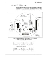
Once the MPS-4100 Microwave system’s wiring has been completed and checked
for correct terminations, power can be applied and the system alignment
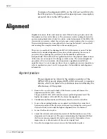
calibrated. Alignment can be calibrated by observing the Alignment aid LED’s
(LD2 - LD11) on the Receiver circuit board. A DC voltage reading of the received
signal strength can be obtained by connecting a voltmeter to TP6 (+) and TP12
(Ground).
Powering up
Relay output version
Apply power to the MPS-4100. Observe that:
•
The power LED illuminates on the Transmitter.
•
Several LED’s illuminate on the Receiver to verify initial operation of the
system.
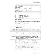
Network version (Silver Network/StarNeT 1000)
Apply power to the MPS-4100. Observe that:
•
LED 1 on the Communication Interface Card illuminates.
•
If the alarm display and control System is configured to poll the MPS-4100
System, the Rec A, Rec B and Xmit LEDs will flash intermittently.
•
Passing your hand in front of the receiver causes a zone 1 detection alarm
(Alm1 LED illuminates).
•
Pressing and releasing the Tamper switch on the receiver causes a Zone 1
supervisory alarm.
When the Tamper switch is pressed, the Sup1 LED is OFF. When
the Tamper switch is released, the Sup1 LED is lit.
Содержание MPS-4100
Страница 1: ...Product MPS 4100 Microwave Protection System Guide E6DA0102 003 Rev C Third Edition April 27 2009 ...
Страница 6: ......
Страница 70: ......


