Relay output wiring
MPS-4100 product guide • • • 2 - 13
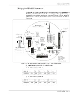
4. Set the Receiver modulation frequency to match the Transmitter modulation
frequency via jumpers JP1 and JP2.
5. Configure the operating parameters via S1 and S2 (see Figure 2-12 and Table
If the Transmitter tamper output is not being wired to the
Receiver, and a tamper output from the Receiver is required,
you must place a jumper across pins 3 & 4 of TB2.
6. You can adjust the alarm relay hold-in time via RV2. The factory default setting
is approximately 1.5 seconds. Clockwise increases the relay hold-in time,
counter-clockwise reduces the hold-in time. The minimum relay hold-in time
is 0.5 seconds and the maximum is 2.5 seconds.
Receiver details
Alarm Relay
Tamper Relay
For N.C. - place a shunt on JP5 pins 1 and 2
For N.O. - place a shunt on JP5 pins 2 and 3
For N.C. 3 K Ohm supervision - place a shunt on
JP6 pins 2 and 3
For N.C. - place a shunt on JP3 pins 1 and 2
For N.O. - place a shunt on JP3 pins 2 and 3
For N.C. 3 K Ohm supervision - place a shunt on
JP4 pins 2 and 3
Table 2-2 Alarm and tamper relay configuration
Figure 2-10 MPS-4100 Receiver circuit board
S1
S2
JP4
JP6
JP5
JP3
JP1
JP2
S3
TAMPER SW
ALARM
JAM
WRONG
CHANNEL
ALIGNMENT
AID LEDs
RED
GREEN
CH6
CH5
CH4
CH3
CH2
CH1
LOCAL
AUDIO
sensitivity
JP7
3K
no 3K
NC
NO
NC NO
FAST SLOW
YELLOW
POOR
BETTER
BEST
TAMPER
ALARM
TP6
TP5
TAMPER
RV3
1 2 3 4 5 6
ON
OFF
1 2 3 4 5 6
ON
OFF
RV2
3K
no 3K
alarm
duration
RV1
TP12
LD12
LD1
LD13
LD11
LD2
MPS-4100
Microwave Receiver
COM
ALM 2
TMPR
TEST 2
COM
AUD 2
TB3
AUD PWR
DATA/
TEST TMP ALM
TB1
+
+
+
XMTTR
CONNECT
TMPR
PWR
TB2
+
P1
Содержание MPS-4100
Страница 1: ...Product MPS 4100 Microwave Protection System Guide E6DA0102 003 Rev C Third Edition April 27 2009 ...
Страница 6: ......
Страница 70: ......

