Coverage pattern
1 - 8 • • • MPS-4100 product guide
planning primer, in Appendix a for information about zone
lengths and maximum beam widths for microwave zones near
metal objects.
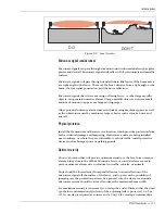
Figure 1-5 provides an example of using offset microwave pairs to eliminate the
dead zone directly in front of the Transmitter/Receiver. Figure 1-5 also
demonstrates the use of a corner overlap to provide complete coverage around a
corner on a protected perimeter.
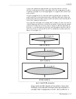
Figure 1-6 illustrates an intermediate offset, which is used to extend the length of
a straight microwave coverage pattern by using two microwave pairs.
Figure 1-5 Dead zone overlap protection (side view)
Figure 1-6 Intermediate overlap (top view)
corner overlap
4.5 m
(15 ft.)
4.5 m
(15 ft.)
full coverage along
dotted lines
4.5 m
(15 ft.)
dead zone
(no coverage)
1
2
unit 1 provides coverage for the
dead zone area of unit 2
top view
beam centerline
offset 46 to 51 cm
(18 to 20 in.)
intermediate overlap
(continuous coverage)
9 m
(30 ft.)
Содержание MPS-4100
Страница 1: ...Product MPS 4100 Microwave Protection System Guide E6DA0102 003 Rev C Third Edition April 27 2009 ...
Страница 6: ......
Страница 70: ......


