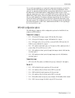
Network wiring (Silver/StarNeT 1000)
MPS-4100 product guide • • • 2 - 19
System configuration
Before installing the Communications Interface Card, install, align and test the
MPS-4100 microwave system.
Installing the Communication Interface Card
No special calibration equipment or tools are required to install the
Communications Interface Card:
•
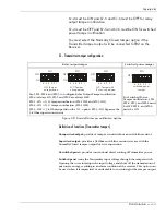
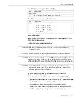
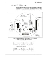
set the network device address and baud rate on the CIC DIP-switches
•
make the network wiring connections on the removable terminal blocks (data
grade shielded cable is recommended) or ST connectors
•
setup the Model MPS-4100 Receiver card for network operation
•
carefully, plug the card into P1 on the Model MPS-4100 Receiver unit PCB
•
attach the ground strap to the ground screw on the enclosure
MPS-4100 input point mapping (Silver Network)
Point
Description
Sensor Alarms
1 - 2
Microwave 1 - 2 (bit 0: Alarm, bit 1: Tamper)
MPS-4100 output point mapping (Silver Network)
Point
Description
Controls
1
Audio Select 1 (Audio 2 LED)
2
Audio Select 2 (Audio 1 LED)
3
Self-Test 1 & 2 (Self-Test LED 1)
4
Self-Test LED 2
WARNING: Disconnect the power source to the MPS-4100 microwave before
installing the card
.
CAUTION: Observe proper ESD handling procedures when working on the card
.
CAUTION: It requires considerable force to install the interface card on P1 of the
MPS-4100 receiver
. Apply firm, even pressure along the card edge
while installing the card. Avoid twisting the card or uneven pressure.
CAUTION: Connect the Interface card ground strap to the ground stud on the
MPS-4100 Receiver enclosure.
A good earth ground is essential for
lightning and transient protection.
Содержание MPS-4100
Страница 1: ...Product MPS 4100 Microwave Protection System Guide E6DA0102 003 Rev C Third Edition April 27 2009 ...
Страница 6: ......
Страница 70: ......

