


Relay output wiring
2 - 12 • • • MPS-4100 product guide
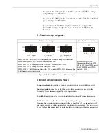
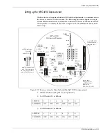
MPS-4100 Receiver wiring
Receiver wiring procedure
1. Connect the power, alarm, tamper, self-test, and audio pairs to TB1
Observe polarity
.
2. Connect the Transmitter power and tamper wires to TB2.
Observe polarity
.
To connect the tamper input from the Transmitter to TB2, the
Transmitter tamper must be set to NC.
3. Configure the alarm and tamper relay outputs via jumpers JP3, JP4, JP5, and
JP6 (see Table 2-2).
Figure 2-9 MPS-4100 Receiver connections for relay output
Audio O/P
self-test I/P (12 VDC)
sensor alarm O/P
Tamper O/P
from Transmitter
tape shield
12 to 24 VDC O/P
to Transmitter
12 to 24 VDC I/P
from power supply
tamper alarm O/P
XMTTR
CONNECT
TMPR
PWR
COM
ALM 2
TMPR
TEST 2
COM
AUD 2
TB3
AUD PWR
DATA/
TEST TMP ALM
TB1
CH6
CH5
CH4
CH3
CH2
CH1
JP1 JP2
P1
S1
ON
OFF
TB2
S2
ON
OFF
+
+
+
+
6
12 4
3 5
MPS-4100
Microwave Receiver
JP7
Fast Slow
6
12 4
3 5
Содержание MPS-4100
Страница 1: ...Product MPS 4100 Microwave Protection System Guide E6DA0102 003 Rev C Third Edition April 27 2009 ...
Страница 6: ......
Страница 70: ......