Alignment
3 - 2 • • • MPS-4100 product guide
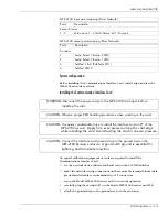
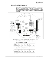
To observe the diagnostic LED’s on the CIC, set switch S2-4 to
the ON position. To operate with reduced power consumption,
set switch S2-4 to the OFF position.
Alignment
Alignment is easier, faster, and more accurate if done by two people, one at the
Transmitter and one at the Receiver. The microwave unit mounting holes in the
post mounting bracket are slotted to enable vertical adjustment of the MPS-4100.
(Loosen the two screws, adjust the vertical aspect, and re-tighten the two screws.)
Horizontal adjustment is accomplished by loosening the bracket’s nut and bolt
and rotating the complete assembly on the mounting post.
There are two methods for aligning the MPS-4100 Microwave system. The first
method is the standard alignment procedure, which optimizes the received
power level by adjusting the positions of the Transmitter and Receiver
independently. This works well in applications where the physical characteristics
of the zone are not expected to change (a stable zone). The second alignment
procedure is for environments, which experience significant snowfall (an
unstable zone). For environments where there is significant snow accumulation,
refer to application notes 1 and 2 in Appendix a for installation and alignment
information.
Alignment procedure
Proper alignment is critical to the reliable operation of the
MPS-4100. A poorly aligned MPS-4100 can result in nuisance
alarms, which can reduce the confidence level and thereby the
effectiveness of the system.
1. Remove the cover from the back of the Receiver unit and observe the
Alignment aid LED’s (LD2 - LD11).
The green LED’s LD4 -LD11 indicate an acceptable alignment level. The
higher the number of the lit LED, the better the alignment.
2. Visually aim the Transmitter and Receiver directly toward each other.
3. Loosen the mounting hardware as required, and adjust the vertical and
horizontal position of the Receiver enclosure by pivoting the unit up and
down and side to side until the highest alignment level is obtained.
4. Secure the Receiver in place.
5. Adjust the vertical and horizontal position of the Transmitter to see if the
alignment can be improved. The person monitoring the Alignment LEDs at
the Receiver must promptly inform the person at the Transmitter of any
improvement or deterioration of the received signal level.
6. Once the best signal is received, secure the Transmitter in place.
Содержание MPS-4100
Страница 1: ...Product MPS 4100 Microwave Protection System Guide E6DA0102 003 Rev C Third Edition April 27 2009 ...
Страница 6: ......
Страница 70: ......


