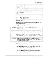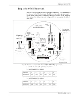
Relay output wiring
MPS-4100 product guide • • • 2 - 11
S1-4 must be ON and S1-5 and S1-6 must be OFF for relay
output tamper notification.
S1-4 must be OFF and S1-5 and S1-6 must be ON for switched
power tamper notification.
You must select the Normally Closed tamper option if the
Transmitter tamper output will be connected to TB2 on the
Receiver.
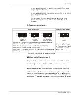
S1 - Transmitter tamper configuration
Definition of functions (Transmitter tamper)
Unsupervised output:
provides a tamper circuit without an end-of-line resistor.
Supervised output:
provides a 3k Ohm end-of-line resistor in series with the
Normally Closed tamper output for wire supervision.
Unswitched power:
provides conventional direct routing of Transmitter power.
Switched power:
runs the Transmitter input voltage through the tamper switch.
Opening the cover interrupts the input voltage and shuts off the transmission of
microwave energy, resulting in an alarm condition at the receiver. This option can
be used when it is impractical or undesirable to run wiring for the tamper output.
Relay output tamper
Switched power tamper
Use SW-1, SW-2 and SW-3 to configure Relay Output Tamper notification.
SW-4 is always ON, SW-5 and SW-6 are always OFF.
SW-1 - ON = N.O. tamper notification (SW-2 OFF and SW-3 ON)
SW-2 - ON = N.C. tamper notification (SW-1 OFF)
SW-3 - OFF = 3 k Ohm supervision for N.C. option; SW-3 - ON bypasses the
3 k Ohm supervision resistor
For Switched Power
Tamper notification - SW-1,
SW-2, SW-3 and SW-4 must
be OFF. SW-5, and SW-6
must be ON.
Figure 2-8 Transmitter tamper notification options
SW1
SW1
ON
OFF
ON
OFF
N.C. Tamper
no supervision
N.O. Tamper
no supervision
6 5 4 3 2 1
6 5 4 3 2 1
SW1
ON
OFF
N.C. Tamper with
3 supervision
k Ohm
6 5 4 3 2 1
SW1
ON
OFF
switched power
tamper
6 5 4 3 2 1
Содержание MPS-4100
Страница 1: ...Product MPS 4100 Microwave Protection System Guide E6DA0102 003 Rev C Third Edition April 27 2009 ...
Страница 6: ......
Страница 70: ......


