Installation planning
2 - 6 • • • MPS-4100 product guide
Receiver S2
•
S2-1 - ON enables audio output via TB3. OFF for audio output via TB1.
•
S2-2 - Not Used.
•
S2-3 - OFF connects tamper for Relay output; ON for network.
•
S2-4 - ON enables Alignment Aid LED’s. OFF disables LED’s.
•
S2-5 - ON enables alarm relay reset. OFF latches alarm relay.
To reset the latching relay, you must open the receiver
enclosure and toggle S2-5.
•
S2-6 - ON enables alarm relay. OFF disables alarm relay.
Receiver jumpers
•
JP1 & JP2 - Selects the modulation frequency Channels 1 through 6.
•
JP3 - Sets tamper output to either Normally Open or Normally Closed.
•
JP4 - Sets the optional 3 k
Ω
end-of-line supervision for tamper NC output.
•
JP5 - Sets the alarm output to either Normally Open or Normally Closed.
•
JP6 - Sets the optional 3 k
Ω
end-of-line supervision for alarm NC output.
•
JP7 - Sets the Receiver’s response to signal disruption to FAST or SLOW.
DIP-switch illustration conventions
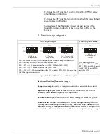
Figure 2-4 illustrates the DIP-switch conventions, used in this guide.
Figure 2-4 DIP-switch conventions
OPEN DIP-switch setting
DIP-switch
CLOSED DIP-switch setting
Illustration
convention
CLOSED
OPEN
Illustration
convention
CLOSED
OPEN
DIP-switch
switch OFF
switch ON
(OPEN = OFF)
(CLOSED = ON)
Содержание MPS-4100
Страница 1: ...Product MPS 4100 Microwave Protection System Guide E6DA0102 003 Rev C Third Edition April 27 2009 ...
Страница 6: ......
Страница 70: ......


