


CRANKCASE\CRANKSHAFT\BALANCE SHAFT
3-4-20
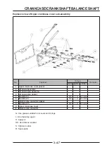
Crankcase assembly
Preparation before assembly:
1. Remove traces of sealant and gaskets from the
crankcase sealing mating surface. Check the surface
for scratches or damage.
2. Remove impurities such as sealant from the bolt
holes.
3. Install the positioning pins into the positioning pin
holes.
4. Check the oil channel to ensure that it is clean and
free of impurities.
◆
According to the crankshaft box, crankshaft, balance
shaft grouping, select the appropriate bearing bush
(see the bearing Bush selection section).
◆
Put the balance shaft bush
【
A
】
and spindle bush
【
B
】
into the corresponding shaft holes of the
upper and lower boxes respectively.
◆
Install crankshaft, balance shaft (refer to crankshaft
connecting rod Piston Assembly, Balance shaft
Assembly section)
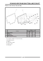
◆
Apply sealant to the sealing surface at the bottom of
the upper crankcase, and the track of the glue line
is as shown in the fi gure. The glue line should be
continuous and uniform.
◆
Align the large end of the connecting rod with the
crankshaft connecting rod journal and install the
corresponding connecting rod cover.
◆
Install connecting rod bolts
【
E
】
and tighten them
as required.
The connecting rod bolt
one step: 25 N·m (2.55 kgf·m, 18.4 ft·lb
ft·lb)
two step
:
45 N·m (4.59 kgf·m, 33 ft·lb
ft·lb)
three step:Turning 60 °
E
E
A
A
C
C
D
D
B
B
B
B
Содержание S301000-20100A
Страница 1: ...SERVICE MANUAL SSV 4 3 4 130 6 54...
Страница 50: ...ENGINE LUBRICATION SYSTEM 3 1 2 Exploded view...
Страница 63: ...EFI SYSTEM 3 2 2 Exploded view Exploded view...
Страница 67: ...STARTING SYSTEM 3 3 2 Exploded view...
Страница 75: ...CRANKCASE CRANKSHAFT BALANCE SHAFT 3 4 2 Explosive view...
Страница 76: ...CRANKCASE CRANKSHAFT BALANCE SHAFT 3 4 3 Explosive view of Up and down the case sub assembly...
Страница 100: ...CYLINDER HEAD CYLINDER PISTON CYLINDER HEAD CYLINDER PISTON 3 5 3 Exploded view...
Страница 102: ...CYLINDER HEAD CYLINDER PISTON CYLINDER HEAD CYLINDER PISTON 3 5 5 Explosive view of Cylinder head sub assembly...
Страница 106: ...CYLINDER HEAD CYLINDER PISTON CYLINDER HEAD CYLINDER PISTON 3 5 9 Explosive view of Piston connecting rod assembly...
Страница 141: ...CVT SYSTEM 3 6 2 Exploded view...
Страница 151: ...WATER PUMP ASSEMBLY 3 7 2 Exploded view...
Страница 197: ...6 6 COOLING SYSTEM SPECIAL TOOLS AND SEALANTS Silicone Sealant Special tools and sealants...
Страница 227: ...9 2 FRONT REAR SUSPENSION EXPLODED VIEW OF FRONT SUSPENSION...
Страница 229: ...9 4 FRONT REAR SUSPENSION EXPLODED VIEW OF REAR SUSPENSION...
Страница 244: ...10 2 WHEELS AND TIRES EXPLODED VIEW OF WHEELS AND TIRES R W R 1 2 5 6 5 6 7 R R R R R W 1 2 3 3 4 3 7 4...
Страница 247: ...10 5 WHEELS AND TIRES SPECIAL TOOLS Jack...
Страница 261: ...11 4 BRAKE SYSTEM SPECIAL TOOLS Inside Circlip Pliers...
Страница 314: ...14 4 ELECTRICAL SYSTEM EXPLODED VIEW...
Страница 407: ...14 97 ELECTRICAL SYSTEM ELECTRIC SCHEMATIC DIAGRAM...


