


2 -
25
MAINTENANCE
PVT / FINAL DRIVE / WHEEL AND TIRE
CVT belt
Replace the CVT drive belt according to the time
specifi ed in the vehicle maintenance schedule. If the CVT
belt is damaged, it should also be replaced.
When replacing the belt, clean the pipe and clutch and
the engine compartment for debris.
!
Failure to remove all debris when the belt is replaced
can result in vehicle damage, loss of control and serious
injury or death
【
A
】
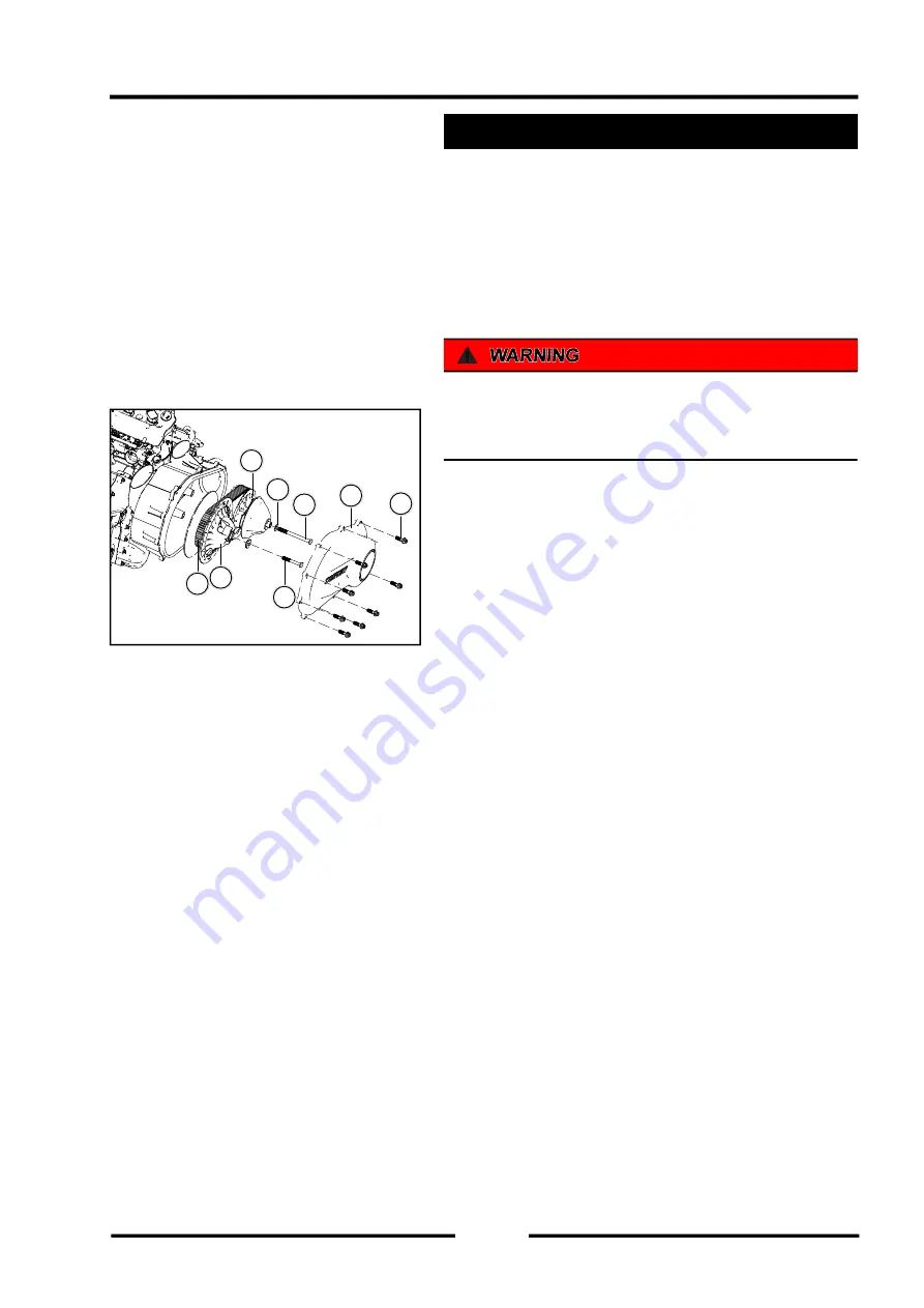
Cover Bolt
【
B
】
CVT Cover
【
C
】
CVT Driving Wheel mounting bolt
【
D
】
Washer
【
E
】
Driving wheel parts
【
F
】
CVT Driven Wheel mounting bolt
【
G
】
Driven wheel parts
【
H
】
CVT belt
Stop the engine before replacement and allow the vehicle
to cool down.
1. Loosen the 10 fastening bolts on the CVT cover and
remove the CVT cover.
2. Loosen the fixing bolts and washers on the CVT
driving wheel component and the driven wheel
respectively.
3. Loosen the fixing bolts and washers on the CVT
driving wheel component and the driven wheel
respectively.
4. Remove the CVT belt to be replaced.
5. Move the driven moving plate assembly forcefully
to increase the gap between the driven and driving
plate, and then install the new CVT belt on the driven
wheel part.
If there are debris in the CVT inner box, please remove
all debris completely.
6. Install the other end of the CVT belt on the driving
wheel, reinstall the driving wheel and driven wheel
A
B
C
D
E
F
G
H
Содержание S301000-20100A
Страница 1: ...SERVICE MANUAL SSV 4 3 4 130 6 54...
Страница 50: ...ENGINE LUBRICATION SYSTEM 3 1 2 Exploded view...
Страница 63: ...EFI SYSTEM 3 2 2 Exploded view Exploded view...
Страница 67: ...STARTING SYSTEM 3 3 2 Exploded view...
Страница 75: ...CRANKCASE CRANKSHAFT BALANCE SHAFT 3 4 2 Explosive view...
Страница 76: ...CRANKCASE CRANKSHAFT BALANCE SHAFT 3 4 3 Explosive view of Up and down the case sub assembly...
Страница 100: ...CYLINDER HEAD CYLINDER PISTON CYLINDER HEAD CYLINDER PISTON 3 5 3 Exploded view...
Страница 102: ...CYLINDER HEAD CYLINDER PISTON CYLINDER HEAD CYLINDER PISTON 3 5 5 Explosive view of Cylinder head sub assembly...
Страница 106: ...CYLINDER HEAD CYLINDER PISTON CYLINDER HEAD CYLINDER PISTON 3 5 9 Explosive view of Piston connecting rod assembly...
Страница 141: ...CVT SYSTEM 3 6 2 Exploded view...
Страница 151: ...WATER PUMP ASSEMBLY 3 7 2 Exploded view...
Страница 197: ...6 6 COOLING SYSTEM SPECIAL TOOLS AND SEALANTS Silicone Sealant Special tools and sealants...
Страница 227: ...9 2 FRONT REAR SUSPENSION EXPLODED VIEW OF FRONT SUSPENSION...
Страница 229: ...9 4 FRONT REAR SUSPENSION EXPLODED VIEW OF REAR SUSPENSION...
Страница 244: ...10 2 WHEELS AND TIRES EXPLODED VIEW OF WHEELS AND TIRES R W R 1 2 5 6 5 6 7 R R R R R W 1 2 3 3 4 3 7 4...
Страница 247: ...10 5 WHEELS AND TIRES SPECIAL TOOLS Jack...
Страница 261: ...11 4 BRAKE SYSTEM SPECIAL TOOLS Inside Circlip Pliers...
Страница 314: ...14 4 ELECTRICAL SYSTEM EXPLODED VIEW...
Страница 407: ...14 97 ELECTRICAL SYSTEM ELECTRIC SCHEMATIC DIAGRAM...


