


14 -
63
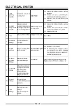
ELECTRICAL SYSTEM
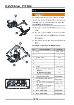
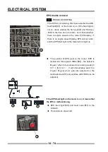
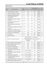
Fault diagnosis
ECU for a variety of sensors, actuators, and power
amplifier and detection circuits
,
To monitor when the
throttle position signal has a fault, the engine may not
have
,
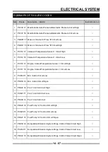
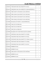
If the method is started or the startup is diffi cult,
the common fault codes can be seen in the General
Table of Fault Codes.
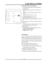
Fault inspection of throttle position sensor and actuator:
◆
Check that the connector is well connected.
◆
Check whether the wire harness and sensor pins
are bent and deformed.
◆
Check the opening and breaking of all stitches (see
the defi nition of stitches in Figure A on the left).
◆
Check whether the supply voltage of pin 5 sensor is
5V.
◆
Check whether pin 1 voltage is 12V.
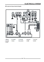
1. electronic throttle body connector on the motor PIN
between the (room temperature) resistance name
Mean value R = 1.4Ω±0.3.
2. I n d u c t a n c e L =1 . 1 ± 0 . 1 M H3 a t 1 K Hz ( r o o m
temperature), working in the opposite direction the
allowable force on: < 200 N.
3. Maximum continuous power loss P = 8 W at ambient
temperature T=100°C
,
The maximum allowable
reversal current I is less than or equal to 10 A during
reversal.
4. Minimum working voltage: 8V
5. rated working voltage: 12V
6. overload working voltage: 17V
Throttle actuator (DC motor) technical
performance parameters
A
Содержание S301000-20100A
Страница 1: ...SERVICE MANUAL SSV 4 3 4 130 6 54...
Страница 50: ...ENGINE LUBRICATION SYSTEM 3 1 2 Exploded view...
Страница 63: ...EFI SYSTEM 3 2 2 Exploded view Exploded view...
Страница 67: ...STARTING SYSTEM 3 3 2 Exploded view...
Страница 75: ...CRANKCASE CRANKSHAFT BALANCE SHAFT 3 4 2 Explosive view...
Страница 76: ...CRANKCASE CRANKSHAFT BALANCE SHAFT 3 4 3 Explosive view of Up and down the case sub assembly...
Страница 100: ...CYLINDER HEAD CYLINDER PISTON CYLINDER HEAD CYLINDER PISTON 3 5 3 Exploded view...
Страница 102: ...CYLINDER HEAD CYLINDER PISTON CYLINDER HEAD CYLINDER PISTON 3 5 5 Explosive view of Cylinder head sub assembly...
Страница 106: ...CYLINDER HEAD CYLINDER PISTON CYLINDER HEAD CYLINDER PISTON 3 5 9 Explosive view of Piston connecting rod assembly...
Страница 141: ...CVT SYSTEM 3 6 2 Exploded view...
Страница 151: ...WATER PUMP ASSEMBLY 3 7 2 Exploded view...
Страница 197: ...6 6 COOLING SYSTEM SPECIAL TOOLS AND SEALANTS Silicone Sealant Special tools and sealants...
Страница 227: ...9 2 FRONT REAR SUSPENSION EXPLODED VIEW OF FRONT SUSPENSION...
Страница 229: ...9 4 FRONT REAR SUSPENSION EXPLODED VIEW OF REAR SUSPENSION...
Страница 244: ...10 2 WHEELS AND TIRES EXPLODED VIEW OF WHEELS AND TIRES R W R 1 2 5 6 5 6 7 R R R R R W 1 2 3 3 4 3 7 4...
Страница 247: ...10 5 WHEELS AND TIRES SPECIAL TOOLS Jack...
Страница 261: ...11 4 BRAKE SYSTEM SPECIAL TOOLS Inside Circlip Pliers...
Страница 314: ...14 4 ELECTRICAL SYSTEM EXPLODED VIEW...
Страница 407: ...14 97 ELECTRICAL SYSTEM ELECTRIC SCHEMATIC DIAGRAM...


