


CYLINDER HEAD, CYLINDER, PISTON
CYLINDER HEAD, CYLINDER, PISTON
3-5-21
!
CAUTION
CAUTION
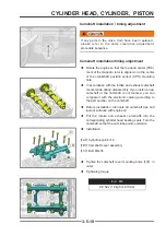
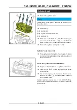
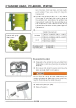
Before installing the camshaft or fi nally assembling the
engine, be sure to check the valve clearance
◆
Camshaft installation (see camshaft installation/
timing adjustment)
◆
Camshaft cover installation (see camshaft
installation/timing adjustment)
◆
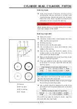
Rotate the camshaft so that the lobes
【
C
】
and
【
D
】
of the cam above the valve to be measured
face up.
◆
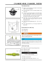
Use a thickness gauge (feel gauge) to measure
the valve clearance
【
A
】
and
【
B
】
. If the gap
exceeds the requirement, record the measurement
result.
◆
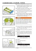
Repeat the above steps until all valves are checked
Valve clearance requirements (cold)
exhaust:
0.2 ~ 0.25mm (0.0079" ~ 0.0098")
Air intake:
0.1 ~ 0.15mm (0.0039" ~ 0.0059")
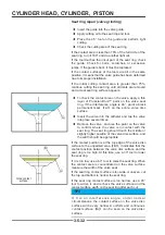
◆
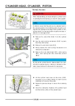
If the valve clearance measurement does not meet
the requirements, please remove the camshaft cover
and camshaft.
◆
Remove the valve lifter that does not meet the valve
clearance requirements.
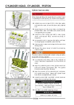
TIPS
In order to ensure that the parts can be installed back to
the original position, the matching parts should be put
together and arranged according to their position on the
cylinder head. The removed parts should be marked or
placed on an arranged shelf.
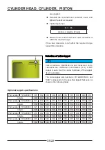
◆
Record the 3 digits
【
A
】
at the bottom of the
tappet.
◆
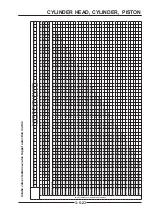
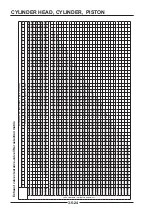
Refer to the tappet selection matrix on the following
page to select a suitable tappet.
◆
Install the selected tappet.
◆
Repeat the above steps until all valve clearances
Valve clearance adjustment
A
A
B
B
C
C
D
D
A
A
Содержание S301000-20100A
Страница 1: ...SERVICE MANUAL SSV 4 3 4 130 6 54...
Страница 50: ...ENGINE LUBRICATION SYSTEM 3 1 2 Exploded view...
Страница 63: ...EFI SYSTEM 3 2 2 Exploded view Exploded view...
Страница 67: ...STARTING SYSTEM 3 3 2 Exploded view...
Страница 75: ...CRANKCASE CRANKSHAFT BALANCE SHAFT 3 4 2 Explosive view...
Страница 76: ...CRANKCASE CRANKSHAFT BALANCE SHAFT 3 4 3 Explosive view of Up and down the case sub assembly...
Страница 100: ...CYLINDER HEAD CYLINDER PISTON CYLINDER HEAD CYLINDER PISTON 3 5 3 Exploded view...
Страница 102: ...CYLINDER HEAD CYLINDER PISTON CYLINDER HEAD CYLINDER PISTON 3 5 5 Explosive view of Cylinder head sub assembly...
Страница 106: ...CYLINDER HEAD CYLINDER PISTON CYLINDER HEAD CYLINDER PISTON 3 5 9 Explosive view of Piston connecting rod assembly...
Страница 141: ...CVT SYSTEM 3 6 2 Exploded view...
Страница 151: ...WATER PUMP ASSEMBLY 3 7 2 Exploded view...
Страница 197: ...6 6 COOLING SYSTEM SPECIAL TOOLS AND SEALANTS Silicone Sealant Special tools and sealants...
Страница 227: ...9 2 FRONT REAR SUSPENSION EXPLODED VIEW OF FRONT SUSPENSION...
Страница 229: ...9 4 FRONT REAR SUSPENSION EXPLODED VIEW OF REAR SUSPENSION...
Страница 244: ...10 2 WHEELS AND TIRES EXPLODED VIEW OF WHEELS AND TIRES R W R 1 2 5 6 5 6 7 R R R R R W 1 2 3 3 4 3 7 4...
Страница 247: ...10 5 WHEELS AND TIRES SPECIAL TOOLS Jack...
Страница 261: ...11 4 BRAKE SYSTEM SPECIAL TOOLS Inside Circlip Pliers...
Страница 314: ...14 4 ELECTRICAL SYSTEM EXPLODED VIEW...
Страница 407: ...14 97 ELECTRICAL SYSTEM ELECTRIC SCHEMATIC DIAGRAM...


