


14 -
66
ELECTRICAL SYSTEM
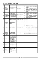
!
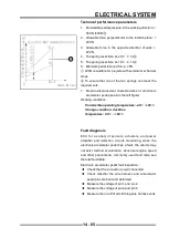
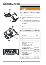
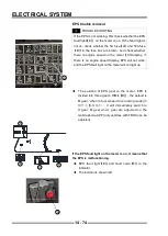
If the vehicle is on without the engine running, then the
failure light will remain on. This is not an indication of
failure and does not require attention.
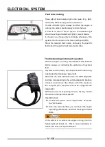
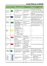
Fault code reading
There is
【
A
】
fault indicator light in the meter (Fig.
【
A
】
on the left). When the key switch is turned on.
Trouble indicator light is always on.When the engine is
running, the vehicle electronically controls the fuel.
If there is no fault in the jet system, the indicator light
should be extinguishedIndicator light in case of failure.
It should be on frequently to indicate a failure of the
system.It can be shown in the meter (left fi gure
【
B
】
).
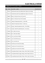
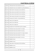
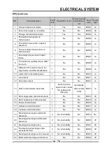
Show the relevant fault codes, and query the specific
fault letters through the fault code master table.
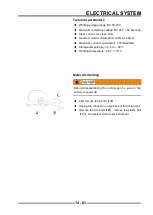
Troubleshooting instrument operation
When the engine is running, the instrument fault indicator
light is always on, indicating the existence of a system
fault.
A system fault.Currently, the phase should be read using
a dedicated fault diagnoser (lower left).
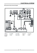
Should be the fault information.Use the OBD diagnostic
interface corresponding to the vehicle diagnostic interface
Connect and connect the other end of the device to
the computer (the computer should be equipped with
diagnostics.
Software and corresponding driver), the key switch
should be in the open state.specifi c.
Operation steps:
◆
Connect the device, select "Open CAN", and press
the "OK" button.
◆
Enter the main interface, you can check the engine
operating parameters and fault message Interest
rates.
A
B
Содержание S301000-20100A
Страница 1: ...SERVICE MANUAL SSV 4 3 4 130 6 54...
Страница 50: ...ENGINE LUBRICATION SYSTEM 3 1 2 Exploded view...
Страница 63: ...EFI SYSTEM 3 2 2 Exploded view Exploded view...
Страница 67: ...STARTING SYSTEM 3 3 2 Exploded view...
Страница 75: ...CRANKCASE CRANKSHAFT BALANCE SHAFT 3 4 2 Explosive view...
Страница 76: ...CRANKCASE CRANKSHAFT BALANCE SHAFT 3 4 3 Explosive view of Up and down the case sub assembly...
Страница 100: ...CYLINDER HEAD CYLINDER PISTON CYLINDER HEAD CYLINDER PISTON 3 5 3 Exploded view...
Страница 102: ...CYLINDER HEAD CYLINDER PISTON CYLINDER HEAD CYLINDER PISTON 3 5 5 Explosive view of Cylinder head sub assembly...
Страница 106: ...CYLINDER HEAD CYLINDER PISTON CYLINDER HEAD CYLINDER PISTON 3 5 9 Explosive view of Piston connecting rod assembly...
Страница 141: ...CVT SYSTEM 3 6 2 Exploded view...
Страница 151: ...WATER PUMP ASSEMBLY 3 7 2 Exploded view...
Страница 197: ...6 6 COOLING SYSTEM SPECIAL TOOLS AND SEALANTS Silicone Sealant Special tools and sealants...
Страница 227: ...9 2 FRONT REAR SUSPENSION EXPLODED VIEW OF FRONT SUSPENSION...
Страница 229: ...9 4 FRONT REAR SUSPENSION EXPLODED VIEW OF REAR SUSPENSION...
Страница 244: ...10 2 WHEELS AND TIRES EXPLODED VIEW OF WHEELS AND TIRES R W R 1 2 5 6 5 6 7 R R R R R W 1 2 3 3 4 3 7 4...
Страница 247: ...10 5 WHEELS AND TIRES SPECIAL TOOLS Jack...
Страница 261: ...11 4 BRAKE SYSTEM SPECIAL TOOLS Inside Circlip Pliers...
Страница 314: ...14 4 ELECTRICAL SYSTEM EXPLODED VIEW...
Страница 407: ...14 97 ELECTRICAL SYSTEM ELECTRIC SCHEMATIC DIAGRAM...


