


9 -
8
FRONT & REAR SUSPENSION
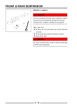
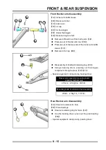
Absorber inspection
Because the front shock absorber is a sealed unit, it
cannot be disassembled,only external inspection is
required. If one unit is damaged, replace two shock
absorbers together as a set. If only one unit is replaced,
when the two shock absorbers are out of balance, it may
cause the vehicle to become unstable at high speeds or
deteriorate the overall comfort.
SHOCK ABSORBER
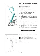
absorber preloading adjustment
【
A
】
crescent wrench
◆
The spring adjusting nut of the air pressure damping
shock absorber is at the upper end of the spring,
and the locking nut is loosened with the tool
【
A
】
.
Then turn the adjusting nut to loosen it.
◆
Adjust the nut position according to the range in the
above table to achieve the desired comfort.
A
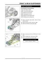
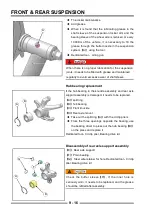
Measure the free length of the spring
【
A
】
lock nut
【
B
】
adjustment nut
【
C
】
Spring preload position
◆
Screw the lock nut
【
A
】
to the required position,
and then unscrew the adjustment nut
【
B
】
, adjust
the position of the nut
【
C
】
Spring preload position
【
C
】
setting standard:
Narrow front Absorber 35mm(1.4in.)
,
usable range 20mm(0.8in.)
~
45mm(1.8in.)
Narrow rear Absorber 130mm(5.1in.)
,
usable range 120mm(4.73in.)
~
150mm(5.9in.)
Wide front Absorber 85mm(3.34in.)
,
usable range 65mm(2.6in.)
~
95mm(3.74in.)
Wide rear Absorber 170mm(6.7in.)
,
usable range 170mm(6.7in.)
~
210mm(8.37in.)
Spring lock nut torque
25 N·m
A
B
C
Содержание S301000-20100A
Страница 1: ...SERVICE MANUAL SSV 4 3 4 130 6 54...
Страница 50: ...ENGINE LUBRICATION SYSTEM 3 1 2 Exploded view...
Страница 63: ...EFI SYSTEM 3 2 2 Exploded view Exploded view...
Страница 67: ...STARTING SYSTEM 3 3 2 Exploded view...
Страница 75: ...CRANKCASE CRANKSHAFT BALANCE SHAFT 3 4 2 Explosive view...
Страница 76: ...CRANKCASE CRANKSHAFT BALANCE SHAFT 3 4 3 Explosive view of Up and down the case sub assembly...
Страница 100: ...CYLINDER HEAD CYLINDER PISTON CYLINDER HEAD CYLINDER PISTON 3 5 3 Exploded view...
Страница 102: ...CYLINDER HEAD CYLINDER PISTON CYLINDER HEAD CYLINDER PISTON 3 5 5 Explosive view of Cylinder head sub assembly...
Страница 106: ...CYLINDER HEAD CYLINDER PISTON CYLINDER HEAD CYLINDER PISTON 3 5 9 Explosive view of Piston connecting rod assembly...
Страница 141: ...CVT SYSTEM 3 6 2 Exploded view...
Страница 151: ...WATER PUMP ASSEMBLY 3 7 2 Exploded view...
Страница 197: ...6 6 COOLING SYSTEM SPECIAL TOOLS AND SEALANTS Silicone Sealant Special tools and sealants...
Страница 227: ...9 2 FRONT REAR SUSPENSION EXPLODED VIEW OF FRONT SUSPENSION...
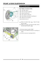
Страница 229: ...9 4 FRONT REAR SUSPENSION EXPLODED VIEW OF REAR SUSPENSION...
Страница 244: ...10 2 WHEELS AND TIRES EXPLODED VIEW OF WHEELS AND TIRES R W R 1 2 5 6 5 6 7 R R R R R W 1 2 3 3 4 3 7 4...
Страница 247: ...10 5 WHEELS AND TIRES SPECIAL TOOLS Jack...
Страница 261: ...11 4 BRAKE SYSTEM SPECIAL TOOLS Inside Circlip Pliers...
Страница 314: ...14 4 ELECTRICAL SYSTEM EXPLODED VIEW...
Страница 407: ...14 97 ELECTRICAL SYSTEM ELECTRIC SCHEMATIC DIAGRAM...


