


CYLINDER HEAD, CYLINDER, PISTON
CYLINDER HEAD, CYLINDER, PISTON
3-5-40
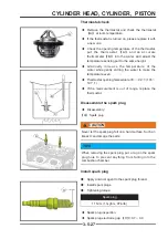
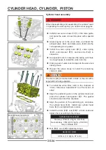
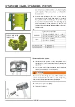
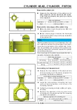
Piston ring installation
TIPS
When installing the piston ring, apply clean engine oil
to the surface. Check the clearance of the piston ring
groove (see "Measuring the clearance of the piston
ring groove"). If assembling a used piston, the carbon
deposits in the piston ring groove and the oil hole of the
oil ring groove should be cleaned fi rst
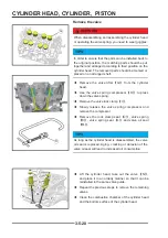
◆
Install the oil ring backing ring
【
B
】
in the bottom
piston ring groove so that the two ends are butt (not
overlapping), and turn the backing ring so that the
opening faces the engine output end.
◆
Install the bottom wiper ring
【
A
】
and turn it so that
the ring port faces the intake side of the piston.
◆
Install the upper wiper ring
【
C
】
and turn it so that
the ring opening faces the exhaust side of the piston.
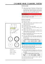
◆
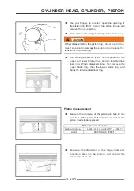
Install the second air ring, the side with the mark on
the ring faces upwards, and turn it so that the ring
opening faces the air inlet side.
◆
Install the first air ring, the side with the mark on
the ring faces upwards, and turn it so that the ring
opening faces the exhaust side.
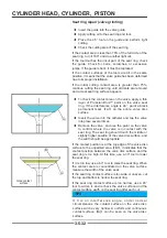
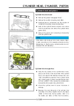
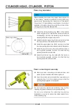
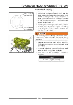
Piston connecting rod assembly
◆
Piston pin hole, connecting rod small end hole, and
piston pin are smeared with clean engine oil.
◆
Insert the piston pin and install the new piston pin
retaining ring. Turn the retaining ring so that the
opening faces upward or downward.
!
CAUTION
CAUTION
Do not reuse the piston pin retaining ring, as the
retaining ring will be deformed during disassembly.
Do not over-compress the retaining ring during
installation, so as not to reduce the radial elastic force
of the retaining ring
E
E
D
D
C
C
B
B
A
A
Arrow towards the
exhaust side
Piston top surface
Output
Intake side
Содержание S301000-20100A
Страница 1: ...SERVICE MANUAL SSV 4 3 4 130 6 54...
Страница 50: ...ENGINE LUBRICATION SYSTEM 3 1 2 Exploded view...
Страница 63: ...EFI SYSTEM 3 2 2 Exploded view Exploded view...
Страница 67: ...STARTING SYSTEM 3 3 2 Exploded view...
Страница 75: ...CRANKCASE CRANKSHAFT BALANCE SHAFT 3 4 2 Explosive view...
Страница 76: ...CRANKCASE CRANKSHAFT BALANCE SHAFT 3 4 3 Explosive view of Up and down the case sub assembly...
Страница 100: ...CYLINDER HEAD CYLINDER PISTON CYLINDER HEAD CYLINDER PISTON 3 5 3 Exploded view...
Страница 102: ...CYLINDER HEAD CYLINDER PISTON CYLINDER HEAD CYLINDER PISTON 3 5 5 Explosive view of Cylinder head sub assembly...
Страница 106: ...CYLINDER HEAD CYLINDER PISTON CYLINDER HEAD CYLINDER PISTON 3 5 9 Explosive view of Piston connecting rod assembly...
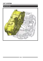
Страница 141: ...CVT SYSTEM 3 6 2 Exploded view...
Страница 151: ...WATER PUMP ASSEMBLY 3 7 2 Exploded view...
Страница 197: ...6 6 COOLING SYSTEM SPECIAL TOOLS AND SEALANTS Silicone Sealant Special tools and sealants...
Страница 227: ...9 2 FRONT REAR SUSPENSION EXPLODED VIEW OF FRONT SUSPENSION...
Страница 229: ...9 4 FRONT REAR SUSPENSION EXPLODED VIEW OF REAR SUSPENSION...
Страница 244: ...10 2 WHEELS AND TIRES EXPLODED VIEW OF WHEELS AND TIRES R W R 1 2 5 6 5 6 7 R R R R R W 1 2 3 3 4 3 7 4...
Страница 247: ...10 5 WHEELS AND TIRES SPECIAL TOOLS Jack...
Страница 261: ...11 4 BRAKE SYSTEM SPECIAL TOOLS Inside Circlip Pliers...
Страница 314: ...14 4 ELECTRICAL SYSTEM EXPLODED VIEW...
Страница 407: ...14 97 ELECTRICAL SYSTEM ELECTRIC SCHEMATIC DIAGRAM...


