


CYLINDER HEAD, CYLINDER, PISTON
CYLINDER HEAD, CYLINDER, PISTON
3-5-42
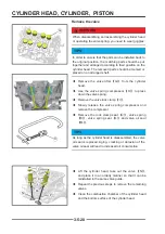
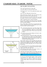
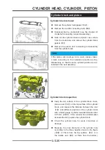
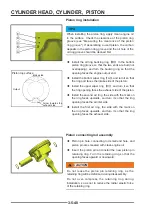
Cylinder pressure measurement
TIPS
Fully charge the battery before measuring
◆
Warm up the engine completely, then stop it.
◆
Disassemble the spark plug (refer to the spark plug chapter).
◆
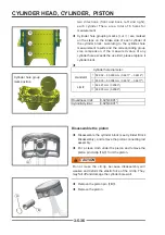
Connect the cylinder pressure gauge and the connector fi rmly to the spark plug hole.
◆
Special tools-cylinder pressure gauge, cylinder pressure gauge connector.
◆
Keep the throttle fully open and use the starter motor to drive the engine several times.
◆
When the pressure gauge stops rising, stop rotating and read the pressure value.
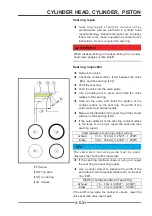
Cylinder pressure (reasonable range)
Electric starter:
1.1 ~ 1.3 MPa (11~13 kgf/cm², 159~188 psi)
If the pressure value obtained is not within a reasonable range, you should refer to the following table.
problem
diagnosis
Measures (actions)
Cylinder pressure
v a l u e i s o u t o f
reasonable range
Due to the valve oil seal and/or piston oil
ring damage, the piston, cylinder head
and combustion chamber produce carbon
deposits (can be determined by the white
smoke exhaust).
Remove carbon deposits
and replace damaged parts if
necessary.
The thickness of the cylinder head gasket is
incorrect.
Replace with standard gaskets.
the valve spring is damaged or the elastic
force fails,
replace the spring.
Cylinder pressure
value is lower than
t h e r e a s o n a b l e
range
Air leakage around the cylinder head
Replace the damaged cylinder
head gasket and check for
deformation of the cylinder
head.
Bad valve seat condition
Repair if necessary.
Incorrect valve clearance
Adjust the valve clearance.
Piston/cylinder hole clearance is
unreasonable.
Check the cylinder block and
replace/repair if necessary
Bad condition of piston ring and/or piston
ring groove
Replace the piston and/or
piston ring.
Содержание S301000-20100A
Страница 1: ...SERVICE MANUAL SSV 4 3 4 130 6 54...
Страница 50: ...ENGINE LUBRICATION SYSTEM 3 1 2 Exploded view...
Страница 63: ...EFI SYSTEM 3 2 2 Exploded view Exploded view...
Страница 67: ...STARTING SYSTEM 3 3 2 Exploded view...
Страница 75: ...CRANKCASE CRANKSHAFT BALANCE SHAFT 3 4 2 Explosive view...
Страница 76: ...CRANKCASE CRANKSHAFT BALANCE SHAFT 3 4 3 Explosive view of Up and down the case sub assembly...
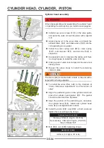
Страница 100: ...CYLINDER HEAD CYLINDER PISTON CYLINDER HEAD CYLINDER PISTON 3 5 3 Exploded view...
Страница 102: ...CYLINDER HEAD CYLINDER PISTON CYLINDER HEAD CYLINDER PISTON 3 5 5 Explosive view of Cylinder head sub assembly...
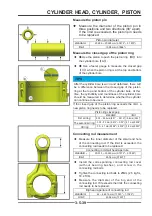
Страница 106: ...CYLINDER HEAD CYLINDER PISTON CYLINDER HEAD CYLINDER PISTON 3 5 9 Explosive view of Piston connecting rod assembly...
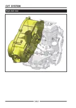
Страница 141: ...CVT SYSTEM 3 6 2 Exploded view...
Страница 151: ...WATER PUMP ASSEMBLY 3 7 2 Exploded view...
Страница 197: ...6 6 COOLING SYSTEM SPECIAL TOOLS AND SEALANTS Silicone Sealant Special tools and sealants...
Страница 227: ...9 2 FRONT REAR SUSPENSION EXPLODED VIEW OF FRONT SUSPENSION...
Страница 229: ...9 4 FRONT REAR SUSPENSION EXPLODED VIEW OF REAR SUSPENSION...
Страница 244: ...10 2 WHEELS AND TIRES EXPLODED VIEW OF WHEELS AND TIRES R W R 1 2 5 6 5 6 7 R R R R R W 1 2 3 3 4 3 7 4...
Страница 247: ...10 5 WHEELS AND TIRES SPECIAL TOOLS Jack...
Страница 261: ...11 4 BRAKE SYSTEM SPECIAL TOOLS Inside Circlip Pliers...
Страница 314: ...14 4 ELECTRICAL SYSTEM EXPLODED VIEW...
Страница 407: ...14 97 ELECTRICAL SYSTEM ELECTRIC SCHEMATIC DIAGRAM...


