


CYLINDER HEAD, CYLINDER, PISTON
CYLINDER HEAD, CYLINDER, PISTON
3-5-17
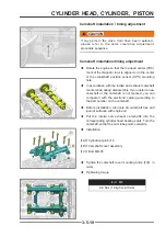
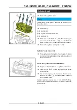
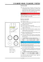
Camshaft sprocket inspection
◆
Check whether the camshaft sprocket teeth are worn
or damaged. If wear or damage is found, replace the
timing chain and sprocket with a new one.
Camshaft / camshaft lobe inspection
◆
Visually check whether the camshaft lobe is worn or
damaged.
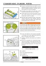
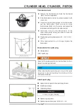
◆
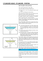
Use a micrometer to measure the height of the
camshaft lobe
【
D
】
.
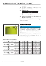
Camshaft lobe height:
Standard
Limit
exhaust
40.08 ± 0.04 mm
(1.5780" ± 0.0015")
39.99 mm (1.5744")
intake
40.36 ± 0.04 mm
(1.5890" ± 0.0015")
40.27 mm (1.5854")
◆
Visually inspect each camshaft journal for scratches,
wear or damage.
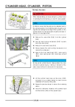
◆
Measure the journal value of the camshaft with a
micrometer and compare with the specifi cation.
Standard
Limit
22.954 ~ 22.975 mm(0.9036" ~ 0.9045") 22.944 mm (0.9033")
TIPS
If the camshaft is damaged or the amount of wear on
any part exceeds the limit, the camshaft should be
replaced
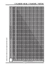
◆
Assemble the camshaft cover separately to measure
the bore of the camshaft bearing. Tighten the bolts in
the specifi ed order.
Camshaft cover bolt
10 N•m (1.0 kgf•m, 89 in•lb)
Standard
Limit
23.000 ~ 23.021 mm(0.9055" ~ 0.9063") 23.044 mm (0.9072")
TIPS
If the camshaft bearing bore is damaged or the amount
of wear exceeds the limit, please replace the cylinder
head assembly
D
D
1
1
10
10
11
11
12
12
7
7
2
2
6
6
3
3
8
8
9
9
4
4
5
5
Содержание S301000-20100A
Страница 1: ...SERVICE MANUAL SSV 4 3 4 130 6 54...
Страница 50: ...ENGINE LUBRICATION SYSTEM 3 1 2 Exploded view...
Страница 63: ...EFI SYSTEM 3 2 2 Exploded view Exploded view...
Страница 67: ...STARTING SYSTEM 3 3 2 Exploded view...
Страница 75: ...CRANKCASE CRANKSHAFT BALANCE SHAFT 3 4 2 Explosive view...
Страница 76: ...CRANKCASE CRANKSHAFT BALANCE SHAFT 3 4 3 Explosive view of Up and down the case sub assembly...
Страница 100: ...CYLINDER HEAD CYLINDER PISTON CYLINDER HEAD CYLINDER PISTON 3 5 3 Exploded view...
Страница 102: ...CYLINDER HEAD CYLINDER PISTON CYLINDER HEAD CYLINDER PISTON 3 5 5 Explosive view of Cylinder head sub assembly...
Страница 106: ...CYLINDER HEAD CYLINDER PISTON CYLINDER HEAD CYLINDER PISTON 3 5 9 Explosive view of Piston connecting rod assembly...
Страница 141: ...CVT SYSTEM 3 6 2 Exploded view...
Страница 151: ...WATER PUMP ASSEMBLY 3 7 2 Exploded view...
Страница 197: ...6 6 COOLING SYSTEM SPECIAL TOOLS AND SEALANTS Silicone Sealant Special tools and sealants...
Страница 227: ...9 2 FRONT REAR SUSPENSION EXPLODED VIEW OF FRONT SUSPENSION...
Страница 229: ...9 4 FRONT REAR SUSPENSION EXPLODED VIEW OF REAR SUSPENSION...
Страница 244: ...10 2 WHEELS AND TIRES EXPLODED VIEW OF WHEELS AND TIRES R W R 1 2 5 6 5 6 7 R R R R R W 1 2 3 3 4 3 7 4...
Страница 247: ...10 5 WHEELS AND TIRES SPECIAL TOOLS Jack...
Страница 261: ...11 4 BRAKE SYSTEM SPECIAL TOOLS Inside Circlip Pliers...
Страница 314: ...14 4 ELECTRICAL SYSTEM EXPLODED VIEW...
Страница 407: ...14 97 ELECTRICAL SYSTEM ELECTRIC SCHEMATIC DIAGRAM...


