


14 -
65
ELECTRICAL SYSTEM
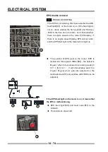
Technical performance parameters
1. Permissible pedal pressure in the working direction: <
500 N (400N
①
).
2. Allowable force perpendicular to the rotation plane: <
200 N
3. Allowable force in the opposite direction of work: <
200 N.
4. The spring reset time at -40
℃
: ≤ 3 s
②
.
5. The spring reset time at -18
℃
: ≤ 1 s
②
.
6. Minimum pedal rebound force: ≥ 5N.
①
400N is suitable for projects with external mechanical
stops.
②
To ensure that one of the two springs can meet the
requirements.
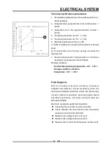
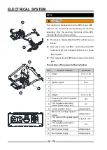
7. Electric-displacement characteristics of electronic
accelerator pedal (see A in the left fi gure)
Working conditions:
Permissible operating temperature: -40
℃
~+85
℃
.
Storage condition: dust-free.
Temperature: -30
℃
~ +60
℃
.
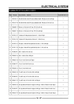
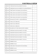
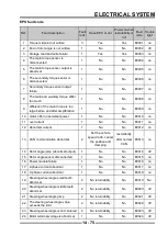
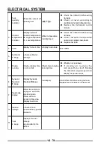
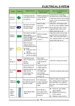
Fault diagnosis
ECU for a variety of sensors, actuators, and power
amplifier and detection circuits monitoring, when the
electronic accelerator pedal has a fault, the vehicle may
not exist method acceleration, abnormal engine speed
and other phenomena, commonly used fault code see
the total fault table:
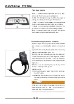
Electronic accelerator pedal fault inspection:
◆
Check that the connector is well connected
◆
Check whether the wire harness and accelerator
pedal pins are bent and deformed
◆
Measure the voltage of pin 1 and pin 2
◆
Measure the voltage of pin 4 and pin 6
◆
Measure the on-off of all stitching wire harness ends
A
Содержание S301000-20100A
Страница 1: ...SERVICE MANUAL SSV 4 3 4 130 6 54...
Страница 50: ...ENGINE LUBRICATION SYSTEM 3 1 2 Exploded view...
Страница 63: ...EFI SYSTEM 3 2 2 Exploded view Exploded view...
Страница 67: ...STARTING SYSTEM 3 3 2 Exploded view...
Страница 75: ...CRANKCASE CRANKSHAFT BALANCE SHAFT 3 4 2 Explosive view...
Страница 76: ...CRANKCASE CRANKSHAFT BALANCE SHAFT 3 4 3 Explosive view of Up and down the case sub assembly...
Страница 100: ...CYLINDER HEAD CYLINDER PISTON CYLINDER HEAD CYLINDER PISTON 3 5 3 Exploded view...
Страница 102: ...CYLINDER HEAD CYLINDER PISTON CYLINDER HEAD CYLINDER PISTON 3 5 5 Explosive view of Cylinder head sub assembly...
Страница 106: ...CYLINDER HEAD CYLINDER PISTON CYLINDER HEAD CYLINDER PISTON 3 5 9 Explosive view of Piston connecting rod assembly...
Страница 141: ...CVT SYSTEM 3 6 2 Exploded view...
Страница 151: ...WATER PUMP ASSEMBLY 3 7 2 Exploded view...
Страница 197: ...6 6 COOLING SYSTEM SPECIAL TOOLS AND SEALANTS Silicone Sealant Special tools and sealants...
Страница 227: ...9 2 FRONT REAR SUSPENSION EXPLODED VIEW OF FRONT SUSPENSION...
Страница 229: ...9 4 FRONT REAR SUSPENSION EXPLODED VIEW OF REAR SUSPENSION...
Страница 244: ...10 2 WHEELS AND TIRES EXPLODED VIEW OF WHEELS AND TIRES R W R 1 2 5 6 5 6 7 R R R R R W 1 2 3 3 4 3 7 4...
Страница 247: ...10 5 WHEELS AND TIRES SPECIAL TOOLS Jack...
Страница 261: ...11 4 BRAKE SYSTEM SPECIAL TOOLS Inside Circlip Pliers...
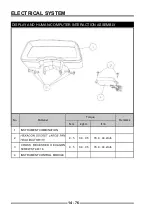
Страница 314: ...14 4 ELECTRICAL SYSTEM EXPLODED VIEW...
Страница 407: ...14 97 ELECTRICAL SYSTEM ELECTRIC SCHEMATIC DIAGRAM...


