


4 -
30
FRONT AXLE AND REAR GEARBOX
FRONT AXLE AND REAR GEARBOX
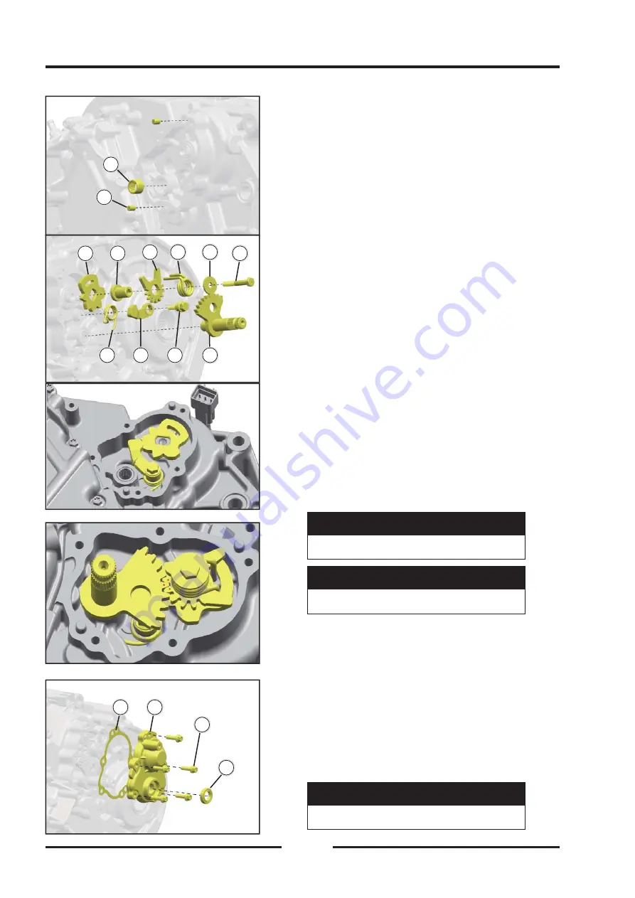
Install the needle bearing and locating pin
【
A
】
Needle roller bearing HK121612
【
B
】
Cylindrical pin 6×10
Tools: Needle bearing indenter-HK121612, copper
hammer.
◆
Press
【
A
】
into the box, and put two cylindrical
pins
【
B
】
into the box.
Install the shift mechanism
【
A
】
Shift positioning wheel
【
F
】
Hexagon head bolt M6×40
【
B
】
Bushing
【
G
】
Shift shaft assembly
【
C
】
Shift driven gear
【
H
】
Positioning plate bolt m6×21
【
D
】
Shift torsion spring
【
I
】
Positioning plate
【
E
】
Washer 6.5×22×2
【
J
】
Shift positioning plate spring
Tool: 10mm sleeve.
◆
Put
【
J
】
into the box, then put
【
I
】
and
【
H
】
into
the box, and then put
【
A
】
into the box and jam
with
【
I
】
as shown in the fi gure.
◆
Install
【
B
】
,
【
C
】
,
【
D
】
,
【
E
】
, and
【
F
】
in
sequence.
◆
Put the installed
【
B
】
,
【
C
】
,
【
D
】
,
【
E
】
, and
【
F
】
into the box and tighten.
◆
Finally, install
【
G
】
as shown in the fi gure to align
the points.
Hexagon head bolt M6×40
15N·m
15N·m(1.53kgf·m,11.1ft·lb)
(1.53kgf·m,11.1ft·lb)
Positioning plate bolt M6×21
15N·m
15N·m(1.53kgf·m,11.1ft·lb)
(1.53kgf·m,11.1ft·lb)
Install the needle bearing and locating pin
【
A
】
Shift shaft cover gasket
【
C
】
Bolt M6×20
【
B
】
Shift shaft cover
【
D
】
Oil seal 15×25×5
◆
Tools: 15×25×, 8mm sleeve for the oil seal pressure
head of the shift chamber cover.
◆
Press
【
D
】
into
【
B
】
, then install
【
A
】
according
to the position of the locating pin, then install
【
B
】
in sequence, and tighten the bolts in sequence.
Bolt M6×20
12N·m
12N·m(1.22kgf·m,8.86ft·lb)
(1.22kgf·m,8.86ft·lb)
AA
BB
BB
AA
C
C
D
D
EE
FF
G
G
H
H
II
JJ
AA
BB
C
C
D
D
Содержание S301000-20100A
Страница 1: ...SERVICE MANUAL SSV 4 3 4 130 6 54...
Страница 50: ...ENGINE LUBRICATION SYSTEM 3 1 2 Exploded view...
Страница 63: ...EFI SYSTEM 3 2 2 Exploded view Exploded view...
Страница 67: ...STARTING SYSTEM 3 3 2 Exploded view...
Страница 75: ...CRANKCASE CRANKSHAFT BALANCE SHAFT 3 4 2 Explosive view...
Страница 76: ...CRANKCASE CRANKSHAFT BALANCE SHAFT 3 4 3 Explosive view of Up and down the case sub assembly...
Страница 100: ...CYLINDER HEAD CYLINDER PISTON CYLINDER HEAD CYLINDER PISTON 3 5 3 Exploded view...
Страница 102: ...CYLINDER HEAD CYLINDER PISTON CYLINDER HEAD CYLINDER PISTON 3 5 5 Explosive view of Cylinder head sub assembly...
Страница 106: ...CYLINDER HEAD CYLINDER PISTON CYLINDER HEAD CYLINDER PISTON 3 5 9 Explosive view of Piston connecting rod assembly...
Страница 141: ...CVT SYSTEM 3 6 2 Exploded view...
Страница 151: ...WATER PUMP ASSEMBLY 3 7 2 Exploded view...
Страница 197: ...6 6 COOLING SYSTEM SPECIAL TOOLS AND SEALANTS Silicone Sealant Special tools and sealants...
Страница 227: ...9 2 FRONT REAR SUSPENSION EXPLODED VIEW OF FRONT SUSPENSION...
Страница 229: ...9 4 FRONT REAR SUSPENSION EXPLODED VIEW OF REAR SUSPENSION...
Страница 244: ...10 2 WHEELS AND TIRES EXPLODED VIEW OF WHEELS AND TIRES R W R 1 2 5 6 5 6 7 R R R R R W 1 2 3 3 4 3 7 4...
Страница 247: ...10 5 WHEELS AND TIRES SPECIAL TOOLS Jack...
Страница 261: ...11 4 BRAKE SYSTEM SPECIAL TOOLS Inside Circlip Pliers...
Страница 314: ...14 4 ELECTRICAL SYSTEM EXPLODED VIEW...
Страница 407: ...14 97 ELECTRICAL SYSTEM ELECTRIC SCHEMATIC DIAGRAM...


