


CYLINDER HEAD, CYLINDER, PISTON
CYLINDER HEAD, CYLINDER, PISTON
3-5-19
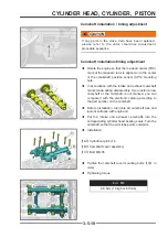
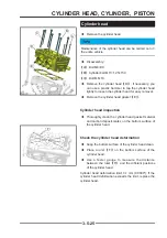
Camshaft installation / timing adjustment
Camshaft installation/timing adjustment
◆
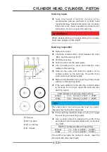
Rotate the engine so that the top dead center (TDC)
mark of the magneto rotor is aligned or in the center
of the crankshaft position sensor (CPS) mounting
hole.
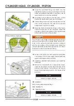
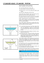
◆
In accordance with the intake and exhaust camshaft
marks made during disassembly. If you install a new
camshaft or the camshaft is not marked, you can
compare it with the electronic catalog according to
the part number on the camshaft.
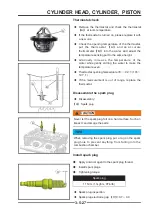
◆
Before installation, lubricate all camshaft tips and
journal surfaces with engine oil.
◆
Put the intake and exhaust camshafts into the
corresponding cylinder head bearing seats. Turn the
camshaft so that the cam lobe points outwards.
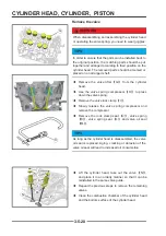
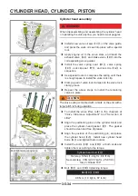
◆
Installation:
【
A
】
Cylindrical pin 6×10
【
B
】
Camshaft cover assembly
【
C
】
Bolt M6×35
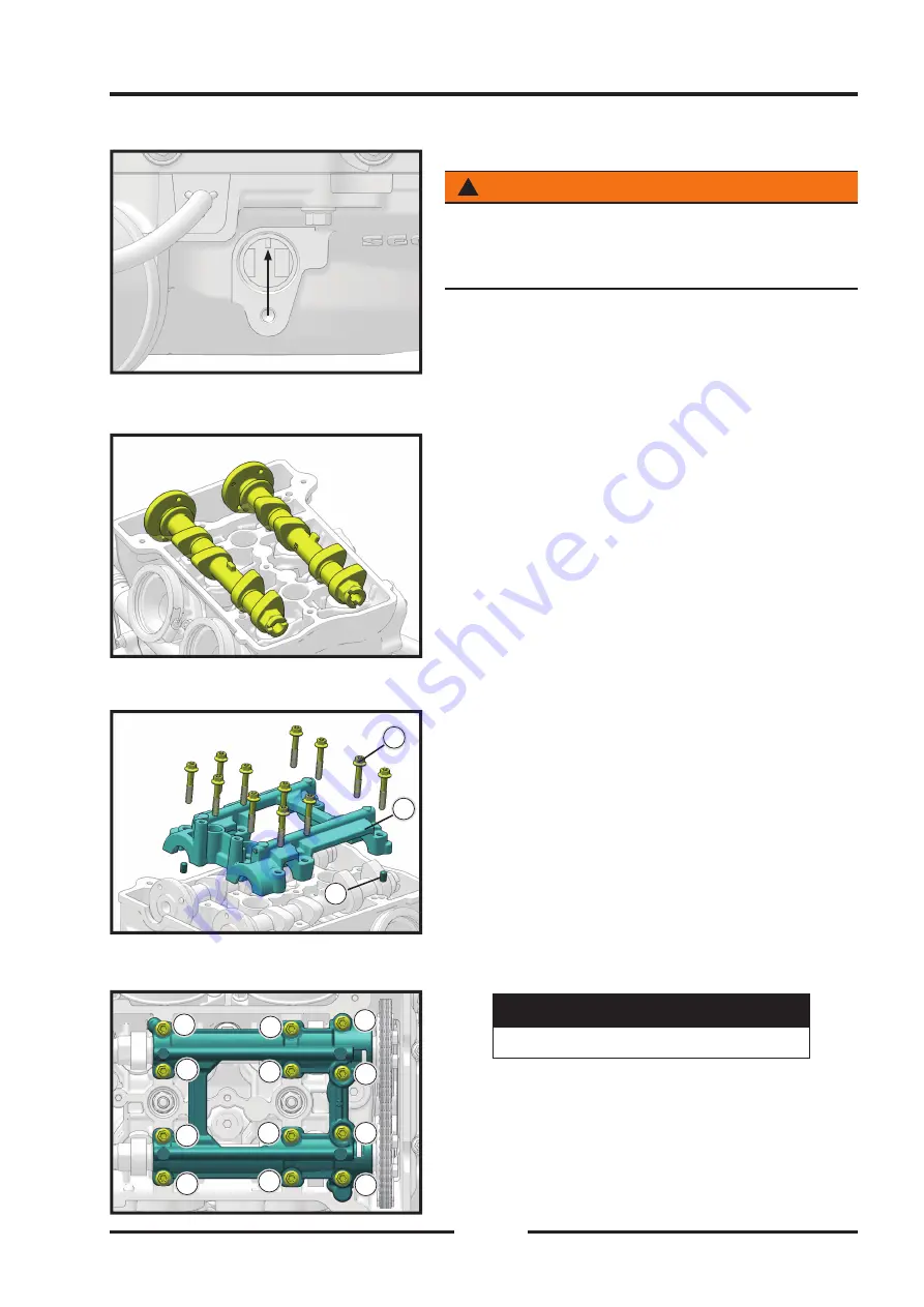
◆
Tighten the camshaft cover mounting bolts
【
C
】
in
order.
◆
Tightening torque
Bolt
M6
9.8 N•m (1.0kgf•m, 87in•lb)
!
CAUTION
CAUTION
If any parts in the valve train have been replaced,
please refer to the valve clearance adjustment
procedure sequence.
11
10
10
11
11
12
12
77
22
66
33
88
99
44
55
C
C
B
B
A
A
Содержание S301000-20100A
Страница 1: ...SERVICE MANUAL SSV 4 3 4 130 6 54...
Страница 50: ...ENGINE LUBRICATION SYSTEM 3 1 2 Exploded view...
Страница 63: ...EFI SYSTEM 3 2 2 Exploded view Exploded view...
Страница 67: ...STARTING SYSTEM 3 3 2 Exploded view...
Страница 75: ...CRANKCASE CRANKSHAFT BALANCE SHAFT 3 4 2 Explosive view...
Страница 76: ...CRANKCASE CRANKSHAFT BALANCE SHAFT 3 4 3 Explosive view of Up and down the case sub assembly...
Страница 100: ...CYLINDER HEAD CYLINDER PISTON CYLINDER HEAD CYLINDER PISTON 3 5 3 Exploded view...
Страница 102: ...CYLINDER HEAD CYLINDER PISTON CYLINDER HEAD CYLINDER PISTON 3 5 5 Explosive view of Cylinder head sub assembly...
Страница 106: ...CYLINDER HEAD CYLINDER PISTON CYLINDER HEAD CYLINDER PISTON 3 5 9 Explosive view of Piston connecting rod assembly...
Страница 141: ...CVT SYSTEM 3 6 2 Exploded view...
Страница 151: ...WATER PUMP ASSEMBLY 3 7 2 Exploded view...
Страница 197: ...6 6 COOLING SYSTEM SPECIAL TOOLS AND SEALANTS Silicone Sealant Special tools and sealants...
Страница 227: ...9 2 FRONT REAR SUSPENSION EXPLODED VIEW OF FRONT SUSPENSION...
Страница 229: ...9 4 FRONT REAR SUSPENSION EXPLODED VIEW OF REAR SUSPENSION...
Страница 244: ...10 2 WHEELS AND TIRES EXPLODED VIEW OF WHEELS AND TIRES R W R 1 2 5 6 5 6 7 R R R R R W 1 2 3 3 4 3 7 4...
Страница 247: ...10 5 WHEELS AND TIRES SPECIAL TOOLS Jack...
Страница 261: ...11 4 BRAKE SYSTEM SPECIAL TOOLS Inside Circlip Pliers...
Страница 314: ...14 4 ELECTRICAL SYSTEM EXPLODED VIEW...
Страница 407: ...14 97 ELECTRICAL SYSTEM ELECTRIC SCHEMATIC DIAGRAM...


