


CYLINDER HEAD, CYLINDER, PISTON
CYLINDER HEAD, CYLINDER, PISTON
3-5-20
◆
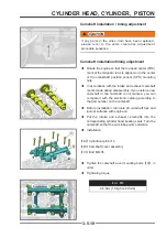
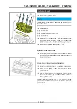
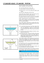
Insert the camshaft fixing tool
【
D
】
into the
camshaft end groove shown in the figure to fix the
intake and exhaust camshafts. If necessary, use an
open-end wrench to turn the camshaft.
◆
According to the method in the first step, confirm
that the top dead center mark has not changed.
◆
Lift the timing chain and snap the sprocket into the
chain. At the same time, the side of the sprocket
marked with "I" and "E" is outside.
◆
Keep the chain tensioned as shown in the figure,
install the sprocket on the camshaft, adjust the
sprocket so that the top surface of the cylinder head
is fl ush with the mark on the sprocke
t
!
CAUTION
CAUTION
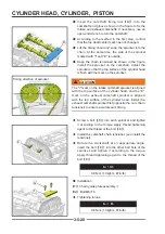
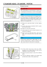
The "I" mark on the intake camshaft sprocket is aligned
with the top surface of the cylinder head, and the "E"
mark on the exhaust camshaft sprocket is aligned
with the top surface of the cylinder head. Install the
exhaust camshaft sprocket fi rst (opposite the cam chain
tensioner) to ensure accurate cam timing.
◆
Screw a bolt
【
E
】
into each sprocket and tighten
it according to the torque. Apply thread tightening
agent to the thread of the bolt
【
E
】
.
◆
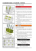
Install the camshaft chain tensioner (see Install the
tensioner).
◆
Rotate the crankshaft at an appropriate angle,
insert the bolt
【
E
】
into the other bolt hole of the
sprocket, and tighten it according to the torque.
Apply thread tightening agent to the thread of the
bolt
【
E
】
.
Bolt
M6
9.8 N•m (1.0kgf•m, 87in•lb)
◆
Installation
【
F
】
Chain guide plate assembly
Ⅱ
【
G
】
Bolt M6×16
◆
Tightening torque
Bolt M6
9.8 N•m (1.0kgf•m, 87in•lb)
G
G
F
F
E
E
D
D
Timing direction of sprocket
Tense
Содержание S301000-20100A
Страница 1: ...SERVICE MANUAL SSV 4 3 4 130 6 54...
Страница 50: ...ENGINE LUBRICATION SYSTEM 3 1 2 Exploded view...
Страница 63: ...EFI SYSTEM 3 2 2 Exploded view Exploded view...
Страница 67: ...STARTING SYSTEM 3 3 2 Exploded view...
Страница 75: ...CRANKCASE CRANKSHAFT BALANCE SHAFT 3 4 2 Explosive view...
Страница 76: ...CRANKCASE CRANKSHAFT BALANCE SHAFT 3 4 3 Explosive view of Up and down the case sub assembly...
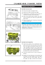
Страница 100: ...CYLINDER HEAD CYLINDER PISTON CYLINDER HEAD CYLINDER PISTON 3 5 3 Exploded view...
Страница 102: ...CYLINDER HEAD CYLINDER PISTON CYLINDER HEAD CYLINDER PISTON 3 5 5 Explosive view of Cylinder head sub assembly...
Страница 106: ...CYLINDER HEAD CYLINDER PISTON CYLINDER HEAD CYLINDER PISTON 3 5 9 Explosive view of Piston connecting rod assembly...
Страница 141: ...CVT SYSTEM 3 6 2 Exploded view...
Страница 151: ...WATER PUMP ASSEMBLY 3 7 2 Exploded view...
Страница 197: ...6 6 COOLING SYSTEM SPECIAL TOOLS AND SEALANTS Silicone Sealant Special tools and sealants...
Страница 227: ...9 2 FRONT REAR SUSPENSION EXPLODED VIEW OF FRONT SUSPENSION...
Страница 229: ...9 4 FRONT REAR SUSPENSION EXPLODED VIEW OF REAR SUSPENSION...
Страница 244: ...10 2 WHEELS AND TIRES EXPLODED VIEW OF WHEELS AND TIRES R W R 1 2 5 6 5 6 7 R R R R R W 1 2 3 3 4 3 7 4...
Страница 247: ...10 5 WHEELS AND TIRES SPECIAL TOOLS Jack...
Страница 261: ...11 4 BRAKE SYSTEM SPECIAL TOOLS Inside Circlip Pliers...
Страница 314: ...14 4 ELECTRICAL SYSTEM EXPLODED VIEW...
Страница 407: ...14 97 ELECTRICAL SYSTEM ELECTRIC SCHEMATIC DIAGRAM...


