


CYLINDER HEAD, CYLINDER, PISTON
CYLINDER HEAD, CYLINDER, PISTON
3-5-34
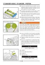
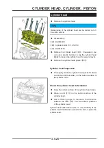
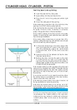
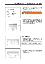
Cylinder head assembly
!
WARNING
When disassembling and assembling the cylinder head
or operating the valve spring, you need to wear goggles.
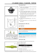
◆
Install a new valve oil seal
【
C
】
on the valve guide,
and press the valve oil seal into place with a special
tool.
◆
Apply engine oil to the valve stem, and insert the
exhaust valve
【
A
】
and intake valve
【
B
】
into the
corresponding valve guides.
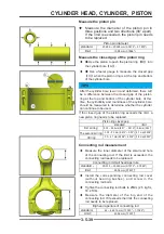
◆
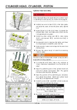
Install the valve spring seat
【
D
】
, valve spring
【
E
】
, lock clip seat
【
F
】
, and lock clip
【
G
】
in
sequence.
◆
Use special tools to compress the spring until there
is enough space to install the valve lock clip.
◆
Clamp a pair of valve lock clamps into the valve lock
clamp groove.
◆
Repeat the above steps to install the remaining
valves in place.
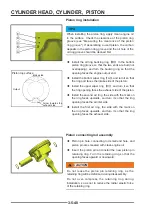
!
CAUTION
CAUTION
The valve spring is marked with a mark or the end with a
larger pitch is facing upwards.
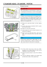
◆
To install the valve lifter, refer to the chapters of
"Valve Clearance Adjustment" and "Selection of
Lifter".
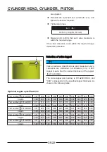
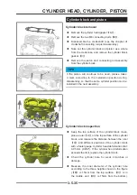
◆
Align the positioning pins on the cylinder block and
place the cylinder head gasket
【
I
】
. The gasket
should be clean and free of grease.
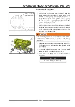
◆
Align the position of the positioning pin, and place
the cylinder head
【
J
】
. Install new cylinder head
bolts
【
L
】
and tighten them in order.
◆
Install the bolts
【
K
】
and
【
M
】
at both ends and
tighten them according to the torque.
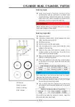
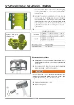
Cylinder head bolt
【
L
】
fi rst step: 12N·m(1.2 kgf·m, 8.8 ft·lb)
Second step
:
35N·m(3.57 kgf·m, 25.8 ft·lb)
Step 3: Rotate 180°
◆
Bolt
【
K
】
and
【
M
】
tightening torque:
Bolt
【
K
】
,
【
M
】
9.8 N·m (1.0 kgf·m, 87 in·lb)
G
G
F
F
E
E
D
D
A
A
C
C
B
B
H
H
11
33
44
66
55
22
M
M
LL
K
K
JJ
II
Bolt tightening sequence
Содержание S301000-20100A
Страница 1: ...SERVICE MANUAL SSV 4 3 4 130 6 54...
Страница 50: ...ENGINE LUBRICATION SYSTEM 3 1 2 Exploded view...
Страница 63: ...EFI SYSTEM 3 2 2 Exploded view Exploded view...
Страница 67: ...STARTING SYSTEM 3 3 2 Exploded view...
Страница 75: ...CRANKCASE CRANKSHAFT BALANCE SHAFT 3 4 2 Explosive view...
Страница 76: ...CRANKCASE CRANKSHAFT BALANCE SHAFT 3 4 3 Explosive view of Up and down the case sub assembly...
Страница 100: ...CYLINDER HEAD CYLINDER PISTON CYLINDER HEAD CYLINDER PISTON 3 5 3 Exploded view...
Страница 102: ...CYLINDER HEAD CYLINDER PISTON CYLINDER HEAD CYLINDER PISTON 3 5 5 Explosive view of Cylinder head sub assembly...
Страница 106: ...CYLINDER HEAD CYLINDER PISTON CYLINDER HEAD CYLINDER PISTON 3 5 9 Explosive view of Piston connecting rod assembly...
Страница 141: ...CVT SYSTEM 3 6 2 Exploded view...
Страница 151: ...WATER PUMP ASSEMBLY 3 7 2 Exploded view...
Страница 197: ...6 6 COOLING SYSTEM SPECIAL TOOLS AND SEALANTS Silicone Sealant Special tools and sealants...
Страница 227: ...9 2 FRONT REAR SUSPENSION EXPLODED VIEW OF FRONT SUSPENSION...
Страница 229: ...9 4 FRONT REAR SUSPENSION EXPLODED VIEW OF REAR SUSPENSION...
Страница 244: ...10 2 WHEELS AND TIRES EXPLODED VIEW OF WHEELS AND TIRES R W R 1 2 5 6 5 6 7 R R R R R W 1 2 3 3 4 3 7 4...
Страница 247: ...10 5 WHEELS AND TIRES SPECIAL TOOLS Jack...
Страница 261: ...11 4 BRAKE SYSTEM SPECIAL TOOLS Inside Circlip Pliers...
Страница 314: ...14 4 ELECTRICAL SYSTEM EXPLODED VIEW...
Страница 407: ...14 97 ELECTRICAL SYSTEM ELECTRIC SCHEMATIC DIAGRAM...


