


CYLINDER HEAD, CYLINDER, PISTON
CYLINDER HEAD, CYLINDER, PISTON
3-5-38
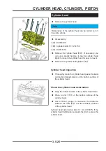
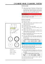
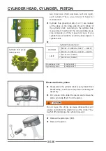
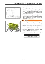
Outer diameter group identifi cation
◆
Check the grouping mark on the top surface of the
piston, and compare the measurement result with
the grouping value of the outer diameter of the
piston. If it exceeds the limit, it needs to be replaced.
Piston diameter
standard
Limit
group
Ⅰ
:
92.951 ~ 92.959 mm
(3.6594" ~ 3.6597")
92.858 mm (3.6558")
group
Ⅱ
:
92.959 ~ 92.967 mm
(3.6597" ~ 3.66")
92.885 mm (3.6569")
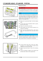
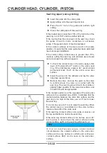
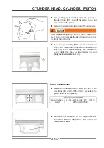
Measure the gap of the piston ring groove
◆
The piston ring should be parallel to the surface of
the piston ring groove. If not, you need to replace
the piston and piston ring.
◆
The piston ring is placed in the piston ring
groove, and the feeler gauge is used for multiple
measurements to determine the piston ring/groove
gap.
Piston ring groove clearance:
Top ring:
0.020 ~ 0.060 mm (0.0007" ~ 0.0023")
second ring:
0.020 ~ 0.060 mm (0.0007" ~ 0.0023")
limit:
0.12 mm (0.0047")
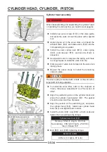
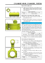
If the piston ring groove gap is greater than the use limit,
measure the thickness of the piston ring and the width
of the ring groove according to the following methods to
determine whether to replace the piston ring or the piston
or at the same time.
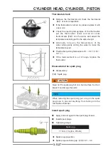
Piston ring groove width
◆
Measure multiple positions on the piston with a
caliper.
Piston ring groove width
standard
Limit
Top ring:
second ring:
1.22 ~ 1.24 mm
(0.0480" ~ 0.0489")
1.31mm
(0.0516")
◆
If the width of any ring groove exceeds the limit, the
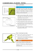
piston needs to be replaced.Piston ring thickness
◆
Use a micrometer to measure multiple positions on
the piston ring.
Piston ring thickness
standard
Limit
Top ring:
second ring:
1.17 ~ 1.19 mm
(0.0461" ~ 0.0469")
1.10mm
(0.0433")
Measuring position
Measuring position
Содержание S301000-20100A
Страница 1: ...SERVICE MANUAL SSV 4 3 4 130 6 54...
Страница 50: ...ENGINE LUBRICATION SYSTEM 3 1 2 Exploded view...
Страница 63: ...EFI SYSTEM 3 2 2 Exploded view Exploded view...
Страница 67: ...STARTING SYSTEM 3 3 2 Exploded view...
Страница 75: ...CRANKCASE CRANKSHAFT BALANCE SHAFT 3 4 2 Explosive view...
Страница 76: ...CRANKCASE CRANKSHAFT BALANCE SHAFT 3 4 3 Explosive view of Up and down the case sub assembly...
Страница 100: ...CYLINDER HEAD CYLINDER PISTON CYLINDER HEAD CYLINDER PISTON 3 5 3 Exploded view...
Страница 102: ...CYLINDER HEAD CYLINDER PISTON CYLINDER HEAD CYLINDER PISTON 3 5 5 Explosive view of Cylinder head sub assembly...
Страница 106: ...CYLINDER HEAD CYLINDER PISTON CYLINDER HEAD CYLINDER PISTON 3 5 9 Explosive view of Piston connecting rod assembly...
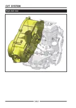
Страница 141: ...CVT SYSTEM 3 6 2 Exploded view...
Страница 151: ...WATER PUMP ASSEMBLY 3 7 2 Exploded view...
Страница 197: ...6 6 COOLING SYSTEM SPECIAL TOOLS AND SEALANTS Silicone Sealant Special tools and sealants...
Страница 227: ...9 2 FRONT REAR SUSPENSION EXPLODED VIEW OF FRONT SUSPENSION...
Страница 229: ...9 4 FRONT REAR SUSPENSION EXPLODED VIEW OF REAR SUSPENSION...
Страница 244: ...10 2 WHEELS AND TIRES EXPLODED VIEW OF WHEELS AND TIRES R W R 1 2 5 6 5 6 7 R R R R R W 1 2 3 3 4 3 7 4...
Страница 247: ...10 5 WHEELS AND TIRES SPECIAL TOOLS Jack...
Страница 261: ...11 4 BRAKE SYSTEM SPECIAL TOOLS Inside Circlip Pliers...
Страница 314: ...14 4 ELECTRICAL SYSTEM EXPLODED VIEW...
Страница 407: ...14 97 ELECTRICAL SYSTEM ELECTRIC SCHEMATIC DIAGRAM...


