


CYLINDER HEAD, CYLINDER, PISTON
CYLINDER HEAD, CYLINDER, PISTON
3-5-29
B
B
A
A
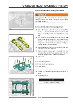
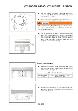
◆
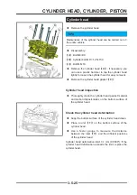
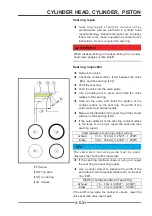
Measure the free length of each valve spring with
a vernier caliper and compare it with the standard
value.
◆
Free length of valve spring:standard:1.726" (43.85
mm)
,
service limit:1.683" (42.75 mm)
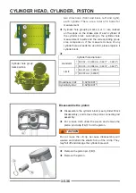
Standard
Limit
42.5 mm (1.6732")
41.4mm (1.6299")
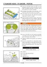
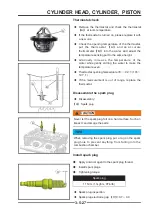
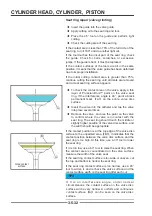
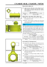
Valve guide / valve inspection
◆
Valve stem clearance measurement:
If there is no small aperture gauge, use the swing method
to measure the gap between the valve and the valve
guide and check the wear of the valve guide. The method
is as follows.
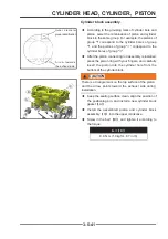
◆
Insert a new valve
【
A
】
into the valve guide
【
B
】
,
and place a dial indicator perpendicular to the valve
stem on the valve stem, as close as possible to the
cylinder head mating surface.
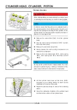
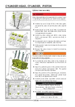
◆
Swing the valve lever to measure the valve/valve
guide gap.
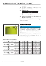
◆
Repeat the measurement in the direction at right
angles to the first direction. If the reading exceeds
the use limit, replace the cylinder head and camshaft
cover assembly.
TIPS
The reading is not the true gap between the valve and
the valve guide, because the measurement position is
above the guide.
Valve/valve guide clearance (swing method)
Standard
Limit
exhaust:
0.09 ~ 0.17 mm(0.0035" ~ 0.0067")
0.34 mm
0.0133"
Air intake:
0.03 ~ 0.11 mm(0.0012" ~ 0.0043")
0.28 mm
0.0110"
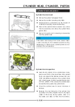
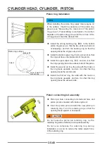
◆
Measure the beating, pitting and ablation of the
valve stem. Check whether the valve rod is bent,
clamp the valve on the machine tool or use a "V"
block and measure it with a dial indicator.
◆
Check whether there is flaring, pitting, abrasion or
damage at the end of the valve stem.
◆
Check whether there is flaring or abrasion at the
lock clip groove. .
Top
bottom
Содержание S301000-20100A
Страница 1: ...SERVICE MANUAL SSV 4 3 4 130 6 54...
Страница 50: ...ENGINE LUBRICATION SYSTEM 3 1 2 Exploded view...
Страница 63: ...EFI SYSTEM 3 2 2 Exploded view Exploded view...
Страница 67: ...STARTING SYSTEM 3 3 2 Exploded view...
Страница 75: ...CRANKCASE CRANKSHAFT BALANCE SHAFT 3 4 2 Explosive view...
Страница 76: ...CRANKCASE CRANKSHAFT BALANCE SHAFT 3 4 3 Explosive view of Up and down the case sub assembly...
Страница 100: ...CYLINDER HEAD CYLINDER PISTON CYLINDER HEAD CYLINDER PISTON 3 5 3 Exploded view...
Страница 102: ...CYLINDER HEAD CYLINDER PISTON CYLINDER HEAD CYLINDER PISTON 3 5 5 Explosive view of Cylinder head sub assembly...
Страница 106: ...CYLINDER HEAD CYLINDER PISTON CYLINDER HEAD CYLINDER PISTON 3 5 9 Explosive view of Piston connecting rod assembly...
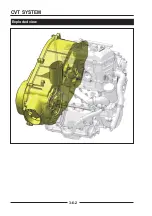
Страница 141: ...CVT SYSTEM 3 6 2 Exploded view...
Страница 151: ...WATER PUMP ASSEMBLY 3 7 2 Exploded view...
Страница 197: ...6 6 COOLING SYSTEM SPECIAL TOOLS AND SEALANTS Silicone Sealant Special tools and sealants...
Страница 227: ...9 2 FRONT REAR SUSPENSION EXPLODED VIEW OF FRONT SUSPENSION...
Страница 229: ...9 4 FRONT REAR SUSPENSION EXPLODED VIEW OF REAR SUSPENSION...
Страница 244: ...10 2 WHEELS AND TIRES EXPLODED VIEW OF WHEELS AND TIRES R W R 1 2 5 6 5 6 7 R R R R R W 1 2 3 3 4 3 7 4...
Страница 247: ...10 5 WHEELS AND TIRES SPECIAL TOOLS Jack...
Страница 261: ...11 4 BRAKE SYSTEM SPECIAL TOOLS Inside Circlip Pliers...
Страница 314: ...14 4 ELECTRICAL SYSTEM EXPLODED VIEW...
Страница 407: ...14 97 ELECTRICAL SYSTEM ELECTRIC SCHEMATIC DIAGRAM...


