


CYLINDER HEAD, CYLINDER, PISTON
CYLINDER HEAD, CYLINDER, PISTON
3-5-35
A
A
B
B
C
C
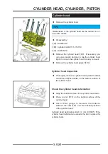
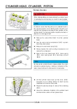
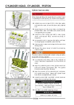
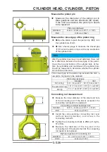
Cylinder block removal
◆
Remove the cylinder head gasket
【
A
】
.
◆
Remove the two M6 connecting bolts
【
B
】
.
◆
Disassemble the crankshaft (see the chapter of
crankshaft connecting rod piston assembly).
◆
Take out the cylinder block and piston as a whole
from the crankcase, and remove the cylinder block
gasket
【
C
】
.
◆
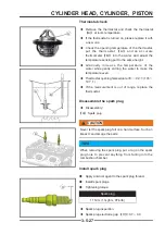
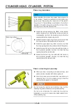
Remove the piston and connecting rod assembly
from the cylinder block.
TIPS
If the piston will continue to be used, please make
a mark according to the installation position during
disassembly, so that the same cylinder position can be
installed in the next assembly.
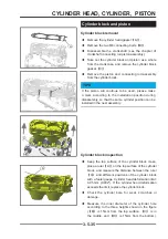
Cylinder block and piston
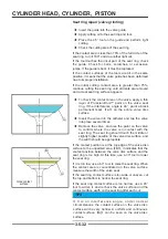
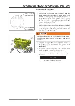
Cylinder block inspection
◆
Keep the top surface of the cylinder block clean,
place a ruler
【
A
】
on the top surface of the cylinder
block, and measure the distance between the ruler
【
A
】
and different positions of the cylinder block
with a feeler gauge. Cylinder head deformation limit:
0.05 mm (0.002"). If the cylinder head deformation
exceeds the limit, replace the cylinder block.
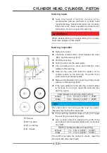
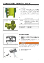
◆
Check the cylinder bore for wear, scratches or
damage.
◆
Measure the inner diameter of the cylinder hole
according to the three heights shown in the figure
(
【
B
】
is 15mm from the top surface,
【
C
】
is in
the middle, and
【
D
】
is 15mm from the bottom),
A
A
Содержание S301000-20100A
Страница 1: ...SERVICE MANUAL SSV 4 3 4 130 6 54...
Страница 50: ...ENGINE LUBRICATION SYSTEM 3 1 2 Exploded view...
Страница 63: ...EFI SYSTEM 3 2 2 Exploded view Exploded view...
Страница 67: ...STARTING SYSTEM 3 3 2 Exploded view...
Страница 75: ...CRANKCASE CRANKSHAFT BALANCE SHAFT 3 4 2 Explosive view...
Страница 76: ...CRANKCASE CRANKSHAFT BALANCE SHAFT 3 4 3 Explosive view of Up and down the case sub assembly...
Страница 100: ...CYLINDER HEAD CYLINDER PISTON CYLINDER HEAD CYLINDER PISTON 3 5 3 Exploded view...
Страница 102: ...CYLINDER HEAD CYLINDER PISTON CYLINDER HEAD CYLINDER PISTON 3 5 5 Explosive view of Cylinder head sub assembly...
Страница 106: ...CYLINDER HEAD CYLINDER PISTON CYLINDER HEAD CYLINDER PISTON 3 5 9 Explosive view of Piston connecting rod assembly...
Страница 141: ...CVT SYSTEM 3 6 2 Exploded view...
Страница 151: ...WATER PUMP ASSEMBLY 3 7 2 Exploded view...
Страница 197: ...6 6 COOLING SYSTEM SPECIAL TOOLS AND SEALANTS Silicone Sealant Special tools and sealants...
Страница 227: ...9 2 FRONT REAR SUSPENSION EXPLODED VIEW OF FRONT SUSPENSION...
Страница 229: ...9 4 FRONT REAR SUSPENSION EXPLODED VIEW OF REAR SUSPENSION...
Страница 244: ...10 2 WHEELS AND TIRES EXPLODED VIEW OF WHEELS AND TIRES R W R 1 2 5 6 5 6 7 R R R R R W 1 2 3 3 4 3 7 4...
Страница 247: ...10 5 WHEELS AND TIRES SPECIAL TOOLS Jack...
Страница 261: ...11 4 BRAKE SYSTEM SPECIAL TOOLS Inside Circlip Pliers...
Страница 314: ...14 4 ELECTRICAL SYSTEM EXPLODED VIEW...
Страница 407: ...14 97 ELECTRICAL SYSTEM ELECTRIC SCHEMATIC DIAGRAM...


