


CYLINDER HEAD, CYLINDER, PISTON
CYLINDER HEAD, CYLINDER, PISTON
3-5-36
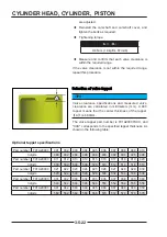
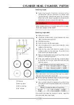
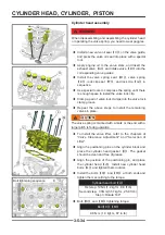
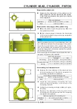
two directions (front and back, left and right),
each cylinder There are a total of 6 holes for
measurement.
◆
Cylinder hole grouping marks (I or
Ⅱ
) are marked
on the steps on the intake side of each cylinder of
the cylinder block. According to the cylinder hole
measurement results and the corresponding group
size comparison, if the measured value of any
cylinder hole exceeds the use limit, please replace it
cylinder block.
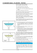
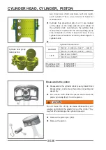
◆
Cylinder hole diameter:
standard:
Ⅰ
92.992 ~ 93.000 mm (3.6611" ~ 3.6614")
Ⅱ
93.000 ~ 93.008 mm (3.6614" ~ 3.6617")
Limit:
Ⅰ
92.927 mm (3.6585")
Ⅱ
99.935 mm (3.6589")
Roundness limit:
0.025(0.001'')
Cylindricity limit:
0.025(0.001'')
B
B
C
C
D
D
Cylinder hole group
mark position
A
A
A
A
B
B
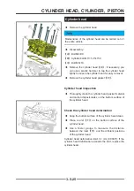
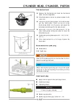
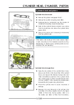
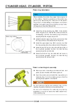
Disassemble the piston
◆
Disassemble the cylinder block (see Cylinder Block
Disassembly), and remove the piston connecting rod
assembly.
◆
Put a clean cloth under the piston and remove the
piston pin circlip
【
A
】
from the piston.
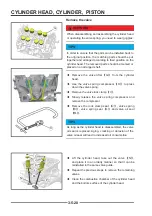
!
CAUTION
CAUTION
Do not reuse the circlip, because disassembly will
weaken and deform the elastic force of the circlip. They
may fall off and damage the cylinder bore wall.
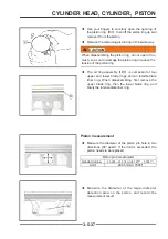
◆
Remove the piston pin
【
B
】
.
◆
Remove the piston.
Содержание S301000-20100A
Страница 1: ...SERVICE MANUAL SSV 4 3 4 130 6 54...
Страница 50: ...ENGINE LUBRICATION SYSTEM 3 1 2 Exploded view...
Страница 63: ...EFI SYSTEM 3 2 2 Exploded view Exploded view...
Страница 67: ...STARTING SYSTEM 3 3 2 Exploded view...
Страница 75: ...CRANKCASE CRANKSHAFT BALANCE SHAFT 3 4 2 Explosive view...
Страница 76: ...CRANKCASE CRANKSHAFT BALANCE SHAFT 3 4 3 Explosive view of Up and down the case sub assembly...
Страница 100: ...CYLINDER HEAD CYLINDER PISTON CYLINDER HEAD CYLINDER PISTON 3 5 3 Exploded view...
Страница 102: ...CYLINDER HEAD CYLINDER PISTON CYLINDER HEAD CYLINDER PISTON 3 5 5 Explosive view of Cylinder head sub assembly...
Страница 106: ...CYLINDER HEAD CYLINDER PISTON CYLINDER HEAD CYLINDER PISTON 3 5 9 Explosive view of Piston connecting rod assembly...
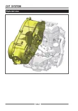
Страница 141: ...CVT SYSTEM 3 6 2 Exploded view...
Страница 151: ...WATER PUMP ASSEMBLY 3 7 2 Exploded view...
Страница 197: ...6 6 COOLING SYSTEM SPECIAL TOOLS AND SEALANTS Silicone Sealant Special tools and sealants...
Страница 227: ...9 2 FRONT REAR SUSPENSION EXPLODED VIEW OF FRONT SUSPENSION...
Страница 229: ...9 4 FRONT REAR SUSPENSION EXPLODED VIEW OF REAR SUSPENSION...
Страница 244: ...10 2 WHEELS AND TIRES EXPLODED VIEW OF WHEELS AND TIRES R W R 1 2 5 6 5 6 7 R R R R R W 1 2 3 3 4 3 7 4...
Страница 247: ...10 5 WHEELS AND TIRES SPECIAL TOOLS Jack...
Страница 261: ...11 4 BRAKE SYSTEM SPECIAL TOOLS Inside Circlip Pliers...
Страница 314: ...14 4 ELECTRICAL SYSTEM EXPLODED VIEW...
Страница 407: ...14 97 ELECTRICAL SYSTEM ELECTRIC SCHEMATIC DIAGRAM...


