


CYLINDER HEAD, CYLINDER, PISTON
CYLINDER HEAD, CYLINDER, PISTON
3-5-39
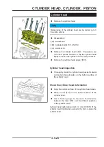
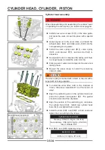
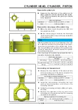
Connecting rod measurement
◆
Measure the inner diameter of the small end hole
of the connecting rod. If the limit is exceeded, the
connecting rod needs to be replaced.
Connecting rod small head aperture
standard
:
20.015 ~ 20.030 mm(0.7879" ~ 0.7885")
limit:
20.06 mm(0.7897")
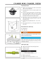
◆
Install the corresponding connecting rod cover
(without bearing bushes), and screw in the
connecting rod bolts.
◆
Tighten the connecting rod bolts to 25Nm (2.5 kgf·m,
18.4 ft·lb).
◆
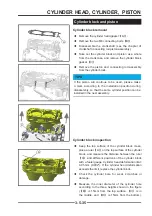
Measure the diameter of the big end of the
connecting rod. If it exceeds the limit, the connecting
rod needs to be replaced.
Big head aperture of connecting rod
standard
:
44 ~ 44.016 mm(1.7323" ~ 1.7329")
Limit::
43.96 mm(1.7307")
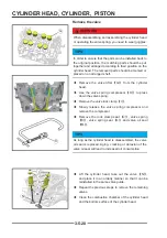
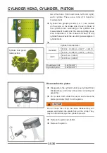
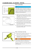
Measure the piston pin
◆
Measure the diameter of the piston pin in
three positions and two directions (90° apart).
If the limit is exceeded, the piston pin needs
to be replaced.
Piston pin diameter
standard
:
20.000 ~ 20.005 mm(0.7873" ~ 0.7875")
limit:
19.98 mm(0.7866")
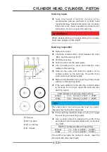
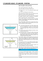
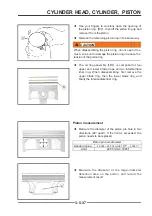
Measure the closed gap of the piston ring
◆
◆
Use the piston to push the piston ring
【
B
】
into
the cylinder bore
【
A
】
.
◆
◆
Use a feeler gauge to measure the closed gap
【
C
】
when the piston ring is at the top and bottom
of the cylinder bore.
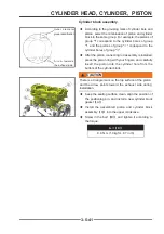
TIPS
After the cylinder bore is worn and deformed, there will
be a difference between the closed gap of the piston
ring at the top and bottom of the cylinder bore. At this
time, the cylindricity and roundness of the cylinder bore
should be measured to determine whether the cylinder
can continue to be used.
If the closed gap of the piston ring exceeds the limit, a
new piston ring needs to be replaced.
Piston ring closed gap
standard
limit
fi rst air ring:
0.25 ~ 0.35 mm(0.01" ~ 0.014") 0.5 mm(0.02")
The second air ring:
0.35 ~ 0.5 mm(0.014" ~ 0.02") 0.7 mm(0.028")
Oil ring
0.2 ~ 0.7 mm(0.008" ~ 0.028") 0.9 mm(0.035")
A
A
B
B
C
C
Содержание S301000-20100A
Страница 1: ...SERVICE MANUAL SSV 4 3 4 130 6 54...
Страница 50: ...ENGINE LUBRICATION SYSTEM 3 1 2 Exploded view...
Страница 63: ...EFI SYSTEM 3 2 2 Exploded view Exploded view...
Страница 67: ...STARTING SYSTEM 3 3 2 Exploded view...
Страница 75: ...CRANKCASE CRANKSHAFT BALANCE SHAFT 3 4 2 Explosive view...
Страница 76: ...CRANKCASE CRANKSHAFT BALANCE SHAFT 3 4 3 Explosive view of Up and down the case sub assembly...
Страница 100: ...CYLINDER HEAD CYLINDER PISTON CYLINDER HEAD CYLINDER PISTON 3 5 3 Exploded view...
Страница 102: ...CYLINDER HEAD CYLINDER PISTON CYLINDER HEAD CYLINDER PISTON 3 5 5 Explosive view of Cylinder head sub assembly...
Страница 106: ...CYLINDER HEAD CYLINDER PISTON CYLINDER HEAD CYLINDER PISTON 3 5 9 Explosive view of Piston connecting rod assembly...
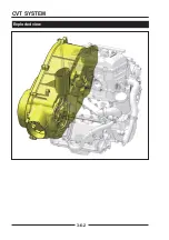
Страница 141: ...CVT SYSTEM 3 6 2 Exploded view...
Страница 151: ...WATER PUMP ASSEMBLY 3 7 2 Exploded view...
Страница 197: ...6 6 COOLING SYSTEM SPECIAL TOOLS AND SEALANTS Silicone Sealant Special tools and sealants...
Страница 227: ...9 2 FRONT REAR SUSPENSION EXPLODED VIEW OF FRONT SUSPENSION...
Страница 229: ...9 4 FRONT REAR SUSPENSION EXPLODED VIEW OF REAR SUSPENSION...
Страница 244: ...10 2 WHEELS AND TIRES EXPLODED VIEW OF WHEELS AND TIRES R W R 1 2 5 6 5 6 7 R R R R R W 1 2 3 3 4 3 7 4...
Страница 247: ...10 5 WHEELS AND TIRES SPECIAL TOOLS Jack...
Страница 261: ...11 4 BRAKE SYSTEM SPECIAL TOOLS Inside Circlip Pliers...
Страница 314: ...14 4 ELECTRICAL SYSTEM EXPLODED VIEW...
Страница 407: ...14 97 ELECTRICAL SYSTEM ELECTRIC SCHEMATIC DIAGRAM...


