www.weg.net
Manual of Electric Motors
105
E
N
G
LI
S
H
To prevent electrical shock, discharge the motor terminals immediately before, and after each
measurement. If the motor is equipped with capacitors, these must be discharged before beginning any
repair.
8.3.1. Terminal box
Proceed as follows to remove the terminal box cover and to disconnect/connect the power supply cables and
the cables of the accessory devices:
g
Ensure that during the screw removal the terminal box cover does not damage the components installed
inside the terminal box;
g
If the terminal box cover is fitted with lifting eyebolt, lift the terminal box cover always by its lift eyebolt;
g
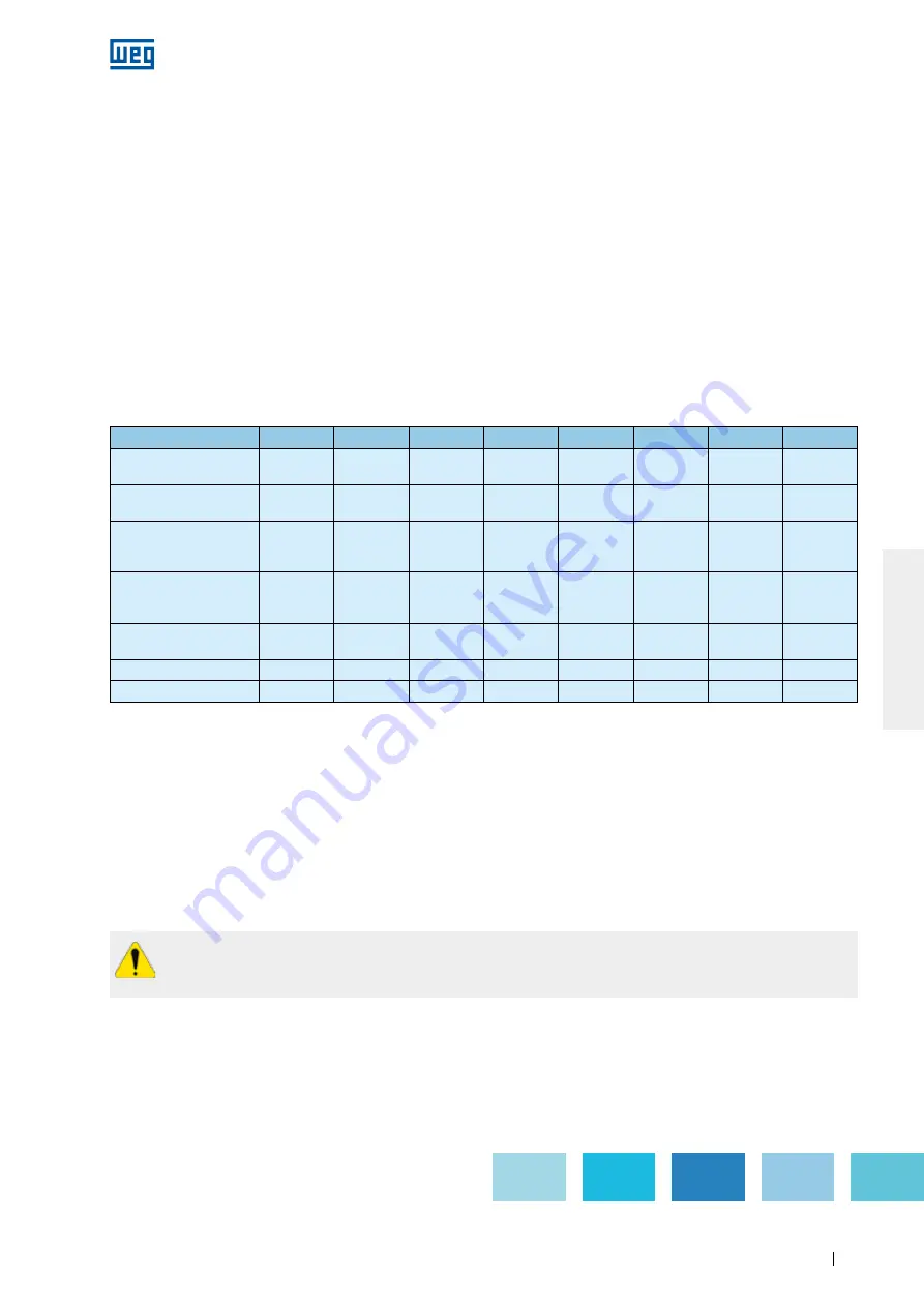
If motors are supplied with terminal blocks, ensure the correct tightening torque on the motor terminals as
specified in Table 8.7;
g
Ensure that the cables do not contact sharp edges;
g
Ensure that the original IP degree of protection is not changed and is maintained as indicate on the motor
nameplate. The power supply cables and the control cables must always be fitted with components (cable
glands, conduits) that meet the applicable standards and regulations of each country;
g
Ensure that the pressure relief device is in perfect operating condition, if provided. The seals in the terminal
box must be in perfect condition for reuse and must be reinstalled correctly to ensure the specified degree of
protection;
g
Ensure the correct tightening torque for the securing bolts of the terminal box cover as specified in Table 8.7.
Table 8.7
- Tightening torque for the securing bolts [Nm]
Screw type and seal
M4
M5
M6
M8
M10
M12
M16
M20
Hex bolt/hex socket bolt
(without seal)
-
4 to 7
7 to 12
16 to 30
30 to 50
55 to 85
120 to 180
230 to 360
Combined slotted screw
(without seal)
-
3 to 5
5 to 10
10 to 18
-
-
-
-
Hex bolt/hex socket bolt
(with seal with metallic
stop/cord)
-
-
-
13 to 20
25 to 37
40 to 55
50 to 65
-
Combined slotted screw
(with flat seal 'and/or
mettallic stop/cord)
-
3 to 5
4 to 8
8 to 15
-
-
-
-
Hex bolt/hex socket bolt
(with flat seal)
-
-
-
8 to 15
18 to 30
25 to 40
35 to 50
-
Terminal blocks
1 to 1,5
1,5 to 4
3 to 6,5
6 to 9
10 to 18
15,5 to 30
30 to 50
-
Grounding terminals
-
3 to 5
5 to 10
10 to 18
30 to 50
55 to 85
120 to 180
-
8.4. DRyING THE STATOR WINDING INSULATION
Dismantle the motor completely. Remove the end shields, the rotor with the shaft, the fan cover, the fan and the
terminal box before the wound stator with the frame is transferred to the oven for the drying process. Place the
wound stator in the oven heated to max. 120 °C for two hours. For larger motors a longer drying time may be
required. After the drying process has been concluded, allow the stator to cool to room temperature. Measure
the insulation resistance again as described in item 5.4. Repeat the stator drying process if the required
insulation resistance does not meet the values specified in Table 5.3. If the insulation resistance does not
improve despite several drying processes, evaluate the causes of the insulation resistance drop carefully and an
eventual replacement of the motor winding may be required. If in doubt contact WEG.
Page 176
Содержание BN 5-12 Series
Страница 13: ...TAB 1 DEVICE DATA SHEETS ...
Страница 18: ...TAB 2 APPROVED SUBMITTAL ...
Страница 23: ...All data subject to change without notice 1 800 ASK 4WEG www weg net 14 ...
Страница 26: ...Your advantages our pumps ...
Страница 45: ...ADV 2 13E And what can we get flowing for you Your nearest contact Or visit www seepex com ...
Страница 117: ...TAB 3 INSTALLATION OPERATIONS AND MAINTENANCE ...
Страница 133: ...Page 37 ...
Страница 233: ...www weg net Manual of Electric Motors 64 ENGLISH Figure 2 1 IEC motor nameplate Page 135 ...
Страница 234: ...www weg net Manual of Electric Motors 65 ENGLISH Figure 2 2 NEMA motor nameplate Page 136 ...
Страница 306: ...TAB 4 AS BUILTS AND SUPPLEMENTAL INFORMATION ...
Страница 307: ...R Page 29 ...
Страница 308: ...R Page 30 ...


