Safety reliably produced.
© RLS Wacon analytics GmbH ∙ +49 (0)5121 28126 0 ∙
Subject to
change without notice
31
Electrical installation
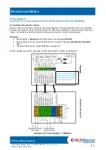
Wiring example 2:
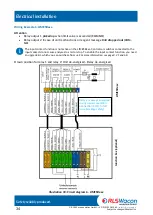
Connection to a reverse osmosis system (connection potential free switch, LIMESPlus)
Connection to an osmosis system:
Relays 1 and 2 are wired as shown in the wiring diagram. In normal operation, there is continuity
between terminals 11 and 6 with this wiring. If a limit value violation or a device fault is detected,
relay 1 or 2 switches and the continuity between terminals 11 and 6 is interrupted.
Attention
•
Relay output 1
picked up
when limit value is exceeded
(COM, NO)
•
Relay output 2 in case of unit malfunctions or reagent message BoB
dropped out
(COM,
NC)
•
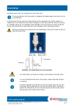
Circuitry of the input contact (INPUT), see page 33
Drawn position for relay 1 and relay 2: Unit de-energised - Relay de-energised
LIMES
Plus
Jun
ct
ion
box
(o
pt
ion
al)
Illustration 15: Circuit diagram 2 - LIMESPlus
Relay 2 is always energized
during normal operation:
Connection COM to NO
(wire breakage safety)
Содержание 32-074165
Страница 76: ......

