72
NOTE:
The following fault codes will
not be stored back-to-back in the
fault buffer. These will only be stored
in the buffer if the previous fault
stored was a different fault. 82, 11,
45, 46 & 57.
CLEARING DIAGNOSTIC
FAULT CODES FROM
THE BUFFER
To clear the fault codes in the fault
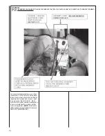
buffer, the dipswitch at position
SW3-3 can be used. Turn the switch
off, on, off, on
or
on, off, on, off
quickly within 30 seconds to reset
the fault codes. When this is done,
the right-most seven-segment dis-
play will energize the upper and
lower horizontal segments for four
seconds as confirmation that the
fault codes have been cleared from
the buffer. Be sure to return the
switch to the original position after
clearing the faults.
Faults can also be cleared at the
furnace User menu under the
Fault
Hist
selection. The seven-segment
displays will again operate as
described above.
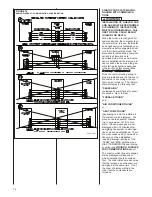
The rightmost decimal on the display
will blink one time for every 100 CFM of
expected airflow whenever the blower
is operating. If the value is actually
less than 50 CFM above any increment
of 100, the value will be rounded to the
lesser 100 value and the lesser value
will be displayed. For example, if the
actual CFM is 1049, the decimal will
blink ten times. If the actual CFM value
is 1051, the decimal will blink eleven
times. For better resolution, a service
tool or communicating thermostat is
required and the expected CFM can be
determined within a resolution of 10
CFM. (See the section of this manual
titled “USER MENUS” under “STATUS
1” or “STATUS 2” submenu “BLOWER
CFM”).
FAULT CODE BUFFER
Upon power reset, the last five fault
codes from the furnace will be dis-
played on the seven-segment display.
These will be displayed in chronological
order from newest (displayed first) to
oldest (displayed last).
For communicating systems, the fault
code buffer can also be read at the
communicating thermostat inside the
furnace User Menus. The most recent
six fault codes are stored. Also dis-
played is the number of days since
each fault code was recorded.
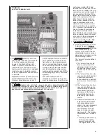
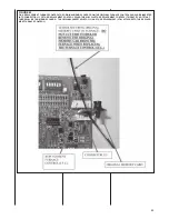
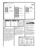
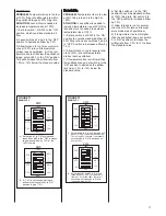
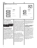
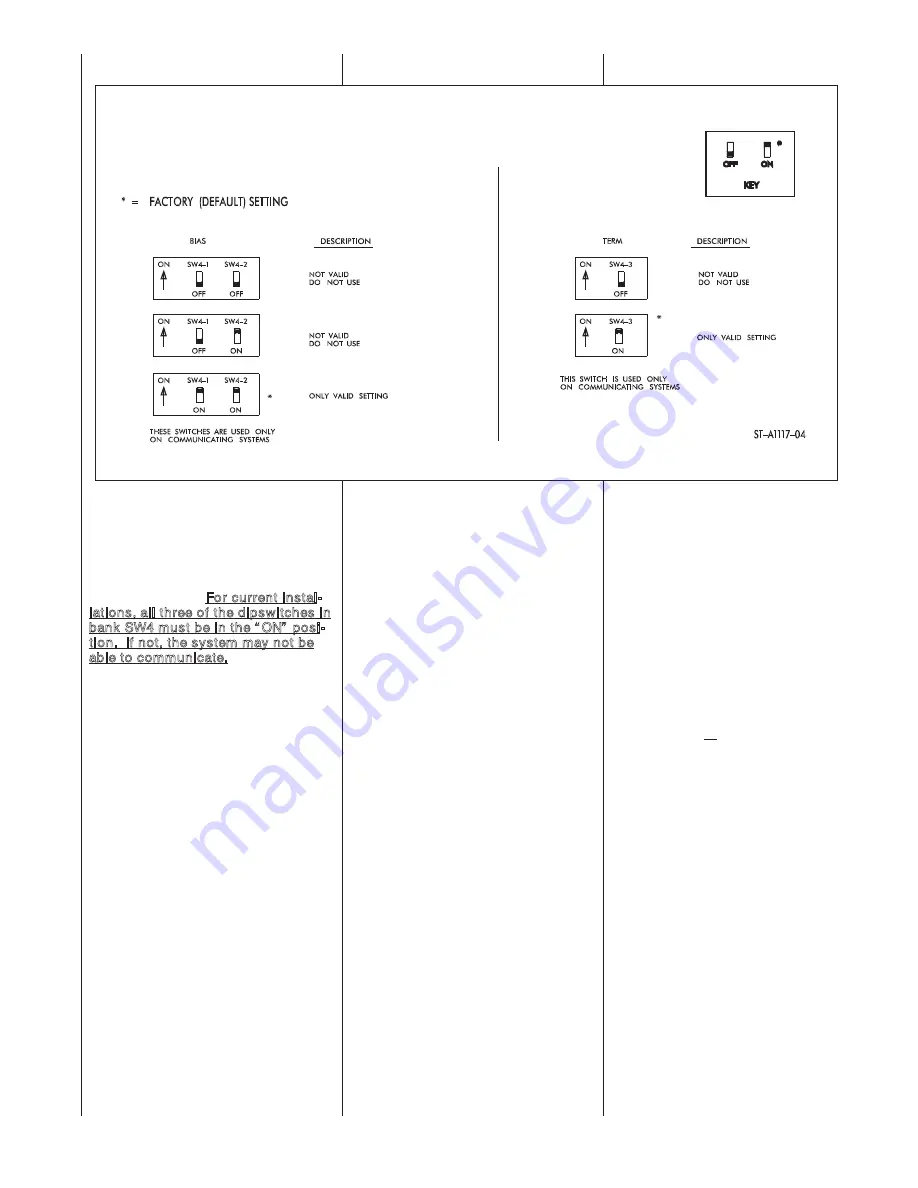
SW4
BIAS / TERMINATION
These dipswitches will not be used for
first generation controls. They are
designed to be used for future genera-
tions of ClimateTalk which may support
multiple networks. For current instal-
lations, all three of the dipswitches in
bank SW4 must be in the “ ON” posi-
tion. If not, the system may not be
able to communicate.
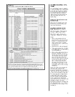
DUAL SEVEN-SEGMENT
DIAGNOSTIC DISPLAY
The dual seven-segment diagnostic dis-
play will either display the status of the
system (e.g. “H” for Heat) or a diagnos-
tic error code in the event of an active
fault. Fault and status codes and their
meanings can be determined from Table
16. For detailed information for each
fault code refer to the TROU-
BLESHOOTING section of this manual.
For communicating systems, the fault
code and a description can be found in
the thermostat “Active Fault” display
area. (See the section of this document
titled “ACTIVE FAULT DISPLAY” under
COMMUNICATING SYSTEMS for more
information).
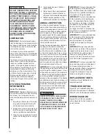
FIGURE 73
DIPSWITCH BANK SW4 TERMINATION AND BIAS SELECTIONS
Содержание RGFE
Страница 92: ...92 TABLE 21 FURNACE FAULT CODES EXPANDED W DESCRIPTIONS AND SOLUTIONS CONTINUED ...
Страница 93: ...93 TABLE 21 FURNACE FAULT CODES EXPANDED W DESCRIPTIONS AND SOLUTIONS CONTINUED ...
Страница 94: ...94 TABLE 21 FURNACE FAULT CODES EXPANDED W DESCRIPTIONS AND SOLUTIONS CONTINUED ...
Страница 95: ...95 TABLE 21 FURNACE FAULT CODES EXPANDED W DESCRIPTIONS AND SOLUTIONS CONTINUED ...
Страница 96: ...96 TABLE 21 FURNACE FAULT CODES EXPANDED W DESCRIPTIONS AND SOLUTIONS CONTINUED ...
Страница 97: ...97 TABLE 21 FURNACE FAULT CODES EXPANDED W DESCRIPTIONS AND SOLUTIONS CONTINUED ...
Страница 98: ...98 TABLE 21 FURNACE FAULT CODES EXPANDED W DESCRIPTIONS AND SOLUTIONS CONTINUED ...
Страница 99: ...99 TABLE 21 FURNACE FAULT CODES EXPANDED W DESCRIPTIONS AND SOLUTIONS CONTINUED ...
Страница 101: ...101 TABLE 21 FURNACE FAULT CODES EXPANDED W DESCRIPTIONS AND SOLUTIONS CONTINUED when the inducer is energized at low ...
Страница 102: ...102 TABLE 21 FURNACE FAULT CODES EXPANDED W DESCRIPTIONS AND SOLUTIONS CONTINUED ...
Страница 103: ...103 TABLE 21 FURNACE FAULT CODES EXPANDED W DESCRIPTIONS AND SOLUTIONS CONTINUED ...
Страница 104: ...104 TABLE 21 FURNACE FAULT CODES EXPANDED W DESCRIPTIONS AND SOLUTIONS CONTINUED ...
Страница 105: ...105 TABLE 21 FURNACE FAULT CODES EXPANDED W DESCRIPTIONS AND SOLUTIONS CONTINUED ...
Страница 106: ...106 FIGURE 83 WIRING DIAGRAM STEPPER MODULATING GAS VALVE FUEL CODE HA OR HB FURNACE MODEL IS RGFE RGGE ...
Страница 107: ...107 FIGURE 84 WIRING DIAGRAM SOLENOID CONTROLLED GAS VALVE FUEL CODE HG OR HH FURNACE MODEL RGGE RGFE RGJF ...

