74
STARTUP FOR SYSTEMS CON-
FIGURED WITH COMMUNICA-
TIONS
INSTALLATION OF LINE VOLTAGE
AND GAS MUST BE PERFORMED
ACCORDING TO INSTRUCTIONS
WRITTEN IN THIS MANUAL. FAIL-
URE TO DO SO COULD RESULT
IN INJURY OR DEATH.
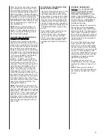
When the furnace is configured for
communications, the components on
the network (i.e. furnace, thermostat
and condenser) must establish com-
munications before engaging a heat
(or other) thermostat demand. The
procedure for establishing communi-
cations is automatic and is
described below. Once communica-
tions is established, the start-up pro-
cedure will be the same as the gen-
eral start-up instructions described
in the section of this manual titled
START-UP PROCEDURES.
Once the communicating wiring is
properly installed and the furnace is
connected to line voltage, the sys-
tem can be turned on. The thermo-
stat will display the following text:
“SEARCHING”
is displayed several times for sever-
al seconds. Next, the text
“FURNACE FOUND”
and
“AIR CONDITIONER FOUND”
or
“HEAT PUMP FOUND”
(depending on which is installed in
the system) will be displayed. The
process can take several minutes
(up to a maximum of 30) to com-
plete. If these messages are not
displayed within 30 minutes after
energizing the system, communica-
tions can not be established. There
are many reasons why communica-
tions may not be established –
including improper settings of the
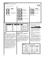
“TERM” and “BIAS” switches (see
BIAS / TERMINATION) and improp-
er wiring (see
WIRING A FURNACE
FOR COMMUNICATIONS
above).
The order in which these messages
will be displayed will depend on
which components are energized
first. The order listed here assumes
that the furnace and condenser are
energized at the same time. If not,
the order of display will be in the
order that the components are
turned on.
!
WARNING
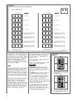
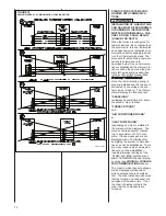
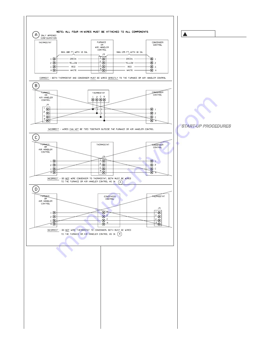
FIGURE 74
WIRING DIAGRAM – COMMUNICATING CONFIGURATION
ST-A-1114-01
Содержание RGFE
Страница 92: ...92 TABLE 21 FURNACE FAULT CODES EXPANDED W DESCRIPTIONS AND SOLUTIONS CONTINUED ...
Страница 93: ...93 TABLE 21 FURNACE FAULT CODES EXPANDED W DESCRIPTIONS AND SOLUTIONS CONTINUED ...
Страница 94: ...94 TABLE 21 FURNACE FAULT CODES EXPANDED W DESCRIPTIONS AND SOLUTIONS CONTINUED ...
Страница 95: ...95 TABLE 21 FURNACE FAULT CODES EXPANDED W DESCRIPTIONS AND SOLUTIONS CONTINUED ...
Страница 96: ...96 TABLE 21 FURNACE FAULT CODES EXPANDED W DESCRIPTIONS AND SOLUTIONS CONTINUED ...
Страница 97: ...97 TABLE 21 FURNACE FAULT CODES EXPANDED W DESCRIPTIONS AND SOLUTIONS CONTINUED ...
Страница 98: ...98 TABLE 21 FURNACE FAULT CODES EXPANDED W DESCRIPTIONS AND SOLUTIONS CONTINUED ...
Страница 99: ...99 TABLE 21 FURNACE FAULT CODES EXPANDED W DESCRIPTIONS AND SOLUTIONS CONTINUED ...
Страница 101: ...101 TABLE 21 FURNACE FAULT CODES EXPANDED W DESCRIPTIONS AND SOLUTIONS CONTINUED when the inducer is energized at low ...
Страница 102: ...102 TABLE 21 FURNACE FAULT CODES EXPANDED W DESCRIPTIONS AND SOLUTIONS CONTINUED ...
Страница 103: ...103 TABLE 21 FURNACE FAULT CODES EXPANDED W DESCRIPTIONS AND SOLUTIONS CONTINUED ...
Страница 104: ...104 TABLE 21 FURNACE FAULT CODES EXPANDED W DESCRIPTIONS AND SOLUTIONS CONTINUED ...
Страница 105: ...105 TABLE 21 FURNACE FAULT CODES EXPANDED W DESCRIPTIONS AND SOLUTIONS CONTINUED ...
Страница 106: ...106 FIGURE 83 WIRING DIAGRAM STEPPER MODULATING GAS VALVE FUEL CODE HA OR HB FURNACE MODEL IS RGFE RGGE ...
Страница 107: ...107 FIGURE 84 WIRING DIAGRAM SOLENOID CONTROLLED GAS VALVE FUEL CODE HG OR HH FURNACE MODEL RGGE RGFE RGJF ...

