GAS PRESSURE
Natural gas supply pressure should
be 5" to 10.5" w.c. LP gas supply
pressure should be 11" to 13" w.c.
This pressure must be maintained
with all other gas-fired appliances in
operation.
NEVER PURGE A GAS LINE INTO
THE COMBUSTION CHAMBER.
NEVER USE MATCHES, FLAME
OR ANY IGNITION SOURCE FOR
CHECKING LEAKAGE. FAILURE
TO ADHERE TO THIS WARNING
CAN CAUSE A FIRE OR EXPLO-
SION RESULTING IN PROPERTY
DAMAGE, PERSONAL INJURY
OR DEATH.
To check for gas leakage, use an
approved chloride-free soap and water
solution, an electronic combustible gas
detector, or other approved method.
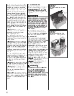
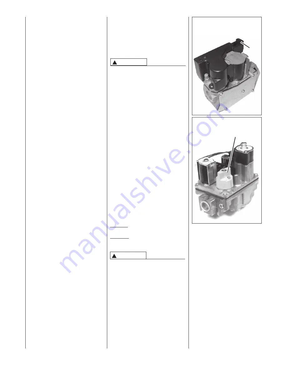
GAS VALVE
This furnace has a 24-volt operated
main solenoid valve. It has ports for
measuring supply pressure and manifold
pressure. A manual control is on the
valve body. It can be set to only the
“ON”
or
“OFF”
positions.
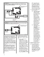
IMPORTANT:
Two different gas valves
are available with the modulating fur-
nace. The type of valve used will affect
the wire diagram, wire assemblies, light-
ing instructions, LP conversion kit and
many other aspects of the furnace
design. To determine the type of valve
used on your furnace, consult the first
two digits of the serial number.
By Serial Number (AKA fuel code)
HA or HB – The valve is a stepper/servo
controlled modulating valve.
HG or HU – The valve is a solenoid-
controlled modulating valve.
See Figures 42 and 43.
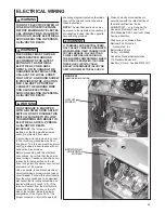
FOR MODULATINIG FURNACES
WITH THE STEPPER/SERVO
CONTROLLED MODULATING
VALVE, DO NOT ROUTE THE
SPARK IGNITOR WIRE (ORANGE)
NEAR THE GAS VALVE. DOING
SO COULD RESULT IN A LOSS
OF HEAT.
!
WARNING
!
WARNING
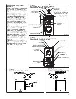
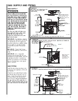
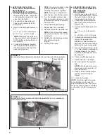
FIGURE 42
GAS VALVE
STEPPER CONTROL-FUEL CODE HA
OR HB
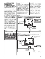
FIGURE 43
GAS VALVE
SOLENOID CONTROL FUEL CODE
HG OR HH
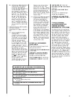
to the combination gas valve on the
furnace.
Refer to Table 8 for the recom-
mended gas pipe size for natural gas
and Table 9 for L.P. See Figures 39, 40
& 41 for typical gas pipe connections.
Install a ground joint union between
the manual gas stop and the main
gas valve to easily remove the con-
trol valve assembly. Install a manual
gas stop in the gas line outside the
furnace cabinet.
The gas stop should
be readily accessible to turn the gas
supply on or off. Install a drip leg in the
gas supply line as close to the furnace
as possible. Always use a pipe com-
pound resistant to the action of liquefied
petroleum gases on all threaded con-
nections.
IMPORTANT:
When making gas pipe
connections, use a back-up wrench to
prevent any twisting of the control
assembly and gas valve.
Any strains on the gas valve can
change the position of the gas orifices in
the burners. This can cause erratic fur-
nace operation.
IMPORTANT:
Do not run a flexible gas
connector inside the unit. If local codes
allow the use of a flexible gas appliance
connector, always use a new listed con-
nector. Do not use a connector which
has previously serviced another gas
appliance. Massachusetts law requires
that all flexible gas connectors be less
than 36”.
The gas pipe grommet in the cabinet
does not seal around a flexible gas con-
nector.
It is important to have all
openings in the cabinet burner com-
partment sealed for proper furnace
operation.
IMPORTANT:
To insure a good seal, the
gas pipe that runs through the grommet
must be 1/2” schedule 40 black pipe.
IMPORTANT:
Ensure that the furnace
gas control valve is not subjected to
high gas line supply pressures (13.5”
w.c. or above).
DISCONNECT
the furnace and its indi-
vidual shut-off valve from the gas supply
piping during
any pressure testing that
exceeds 1/2 PSIG (3.23 kPa or 13"
w.c.).
ON/OFF
SWITCH
MANUAL CONTROL
40
Содержание RGFE
Страница 92: ...92 TABLE 21 FURNACE FAULT CODES EXPANDED W DESCRIPTIONS AND SOLUTIONS CONTINUED ...
Страница 93: ...93 TABLE 21 FURNACE FAULT CODES EXPANDED W DESCRIPTIONS AND SOLUTIONS CONTINUED ...
Страница 94: ...94 TABLE 21 FURNACE FAULT CODES EXPANDED W DESCRIPTIONS AND SOLUTIONS CONTINUED ...
Страница 95: ...95 TABLE 21 FURNACE FAULT CODES EXPANDED W DESCRIPTIONS AND SOLUTIONS CONTINUED ...
Страница 96: ...96 TABLE 21 FURNACE FAULT CODES EXPANDED W DESCRIPTIONS AND SOLUTIONS CONTINUED ...
Страница 97: ...97 TABLE 21 FURNACE FAULT CODES EXPANDED W DESCRIPTIONS AND SOLUTIONS CONTINUED ...
Страница 98: ...98 TABLE 21 FURNACE FAULT CODES EXPANDED W DESCRIPTIONS AND SOLUTIONS CONTINUED ...
Страница 99: ...99 TABLE 21 FURNACE FAULT CODES EXPANDED W DESCRIPTIONS AND SOLUTIONS CONTINUED ...
Страница 101: ...101 TABLE 21 FURNACE FAULT CODES EXPANDED W DESCRIPTIONS AND SOLUTIONS CONTINUED when the inducer is energized at low ...
Страница 102: ...102 TABLE 21 FURNACE FAULT CODES EXPANDED W DESCRIPTIONS AND SOLUTIONS CONTINUED ...
Страница 103: ...103 TABLE 21 FURNACE FAULT CODES EXPANDED W DESCRIPTIONS AND SOLUTIONS CONTINUED ...
Страница 104: ...104 TABLE 21 FURNACE FAULT CODES EXPANDED W DESCRIPTIONS AND SOLUTIONS CONTINUED ...
Страница 105: ...105 TABLE 21 FURNACE FAULT CODES EXPANDED W DESCRIPTIONS AND SOLUTIONS CONTINUED ...
Страница 106: ...106 FIGURE 83 WIRING DIAGRAM STEPPER MODULATING GAS VALVE FUEL CODE HA OR HB FURNACE MODEL IS RGFE RGGE ...
Страница 107: ...107 FIGURE 84 WIRING DIAGRAM SOLENOID CONTROLLED GAS VALVE FUEL CODE HG OR HH FURNACE MODEL RGGE RGFE RGJF ...


