background image

122

However, after a two-hour period,

this will change and the thermostat

will take as long as five minutes for

every degree F to change the dis-

play. Therefore, for example a rapid

change of five degrees in room tem-

perature will not be correctly indicat-

ed at the thermostat for (up to) 25

minutes. This is done to buffer the

thermostat against rapid and insignif-

icant swings in temperature caused

by briefly opening a door or window.

This operation prevents excessive

cycling of the thermostat and is a

feature used in all modern ther-

mostats.

COMMUNICATING THERMOSTATS

COMMUNICATING THER-

MOSTATS

The modulating furnace is capable of

communicating with a thermostat and

condenser to improve cooling and heat-

pump airflow, displaying active faults

and active furnace information at the

thermostat and improved diagnostics

and troubleshooting.

WIRING A FURNACE FOR

COMMUNICATIONS.

MAXIMUM COMMUNICATING WIRE

LENGTHS (1, 2, R & C)

Max Wire Length – Thermostat to

Furnace = 100 FT @ 18 AWG*

Max Wire Length – Furnace to

Condenser = 125 FT @ 18 AWG*
Notes:
1. When using twisted pairs, be sure the

wires connected to pins labeled “1”

(recommended wire color = green)

and “2” (recommended wire color =

yellow) are a twisted pair.

2. Wires may be solid or stranded.
3. *Wire gage smaller than 18 AWG is

not approved or recommended for

this application.

4. When using existing wire from a pre-

vious installation, be sure to trim the

tip of the wire back past the insulation

and strip a small amount of insulation

from the wire to expose clean new

copper for the communicating con-

nections.  Fresh copper must be

exposed when making the communi-

cating connections or communications

may not be properly established.

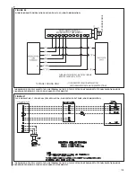
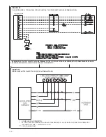
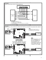
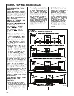
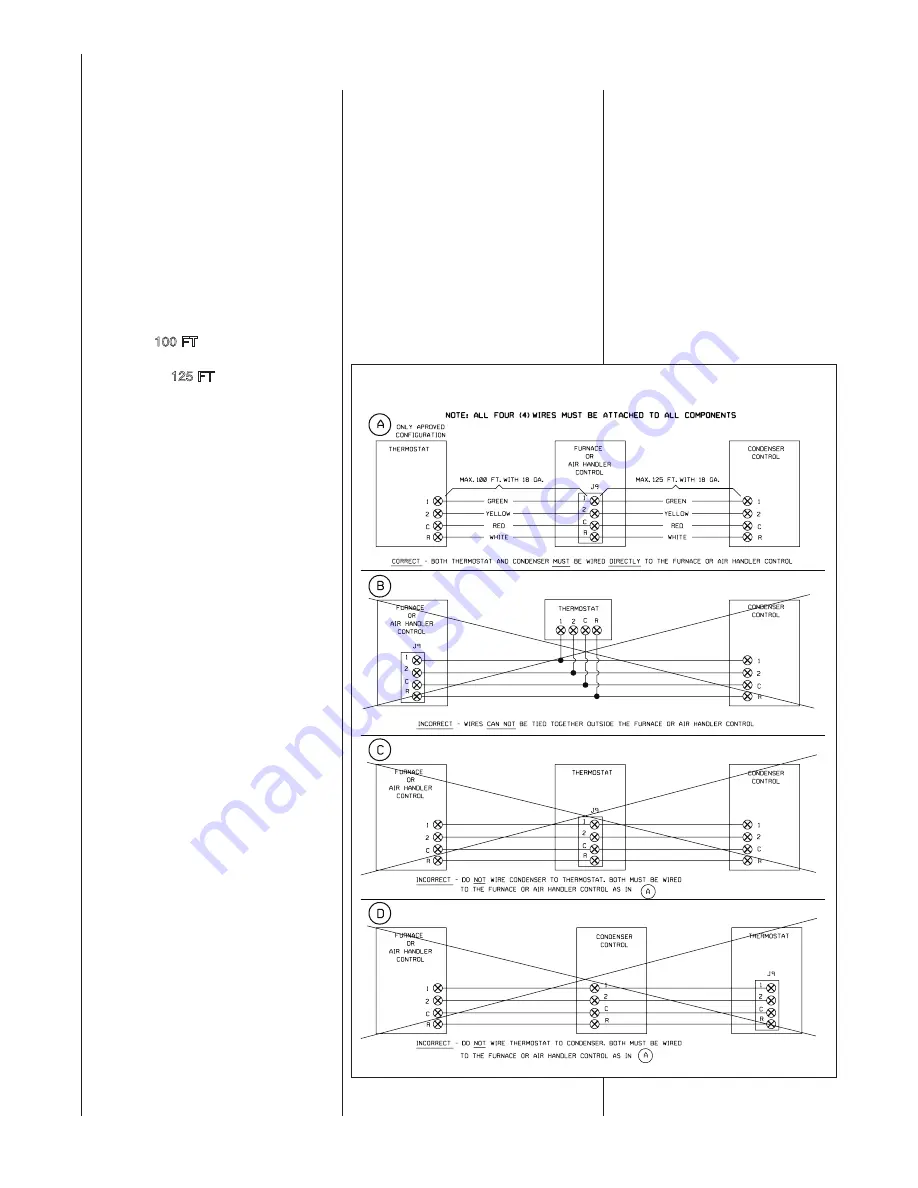
Figures 96 through 97 below are wiring

diagrams for connecting the furnace to

an approved ClimateTalk communicat-

ing thermostat and approved Rheem or

Ruud communicating condenser.
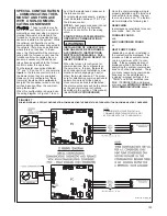
The only approved configuration for

fully communicating systems is to install

dedicated wires directly from the fur-

nace to the thermostat and a separate

set of dedicated wires directly from the

furnace to the condenser.  Note:  The

only approved configuration for systems

with a communicating condenser

requires that four dedicated wires (1, 2,

R and C) be installed from the furnace

to the condenser.

TWO NOTES ABOUT COM-

MUNICATING THER-

MOSTATS

1. When power to the thermostat has

been reset and/or the batteries are

replaced, the thermostat will respond

quickly to changes in room tempera-

ture as indicated by the room tem-

perature displayed at the thermostat.

2. For dual-fuel systems, once the

thermostat has switched over to

auxiliary heat (e.g. gas heat), sub-

sequent heat calls may also

immediatel

y begin with auxiliary

heat regardless of the dual-fuel

changeover point and the actual

outdoor temperature or the differ-

ence between room temperatures

and setpoint. This is true as long

as the subsequent heat call is

within 12 minutes or less of end

of the previous heat call. The

actual time between heat calls

that will cause this operation

varies but should not exceed 12

minutes.

FIGURE 96

WIRING DIAGRAM – COMMUNICATING CONFIGURATION

A-1114-01

Содержание RGFE

Страница 1: ...lier s instructions If you cannot reach your gas supplier call the fire department Do not return to your home until authorized by the gas supplier or fire department DO NOT RELY ON SMELL ALONE TO DETECT LEAKS DUE TO VARIOUS FACTORS YOU MAY NOT BE ABLE TO SMELL FUEL GASES U L recognized fuel gas and CO detectors are recommended in all applications and their installa tion should be in accordance wit...

Страница 2: ...ROUBLESHOOTING CHART 87 NORMAL OPERATING CODES TABLE 20 89 FURNACE FAULT CODES WITH DESCRIPTIONS AND SOLUTIONS TABLE 21 90 105 WIRE DIAGRAM STEPPER SERVO MODULATING VALVE FUEL CODES HA OR HB 106 WIRE DIAGRAM SOLENOID CONTROLLED MODULATING VALVE FUEL CODES HG OR HH 107 THERMOSTATS 108 NON COMMUNICATING THERMOSTATS 108 THERMOSTAT WIRING WITH WIRING DIAGRAMS 109 APPLICATIONS 112 MODULATING TOUCH SCRE...

Страница 3: ...ing said thirty 30 day period a battery operated carbon monoxide detector with an alarm shall be installed 2 APPROVED CARBON MONOXIDE DETECTORS Each carbon monoxide detector as required in accordance with the above provisions shall comply with NFPA 720 and be ANSI UL 2034 listed and IAS certified 3 SIGNAGE A metal or plastic identifi cation plate shall be permanently mount ed to the exterior of th...

Страница 4: ...THE RISK OF IGNITING FLAMMABLE VAPORS WHICH MAY BE PRESENT IN A GARAGE ALSO THE FURNACE MUST BE LOCATED OR PROTECTED TO AVOID PHYSICAL DAMAGE BY VEHI CLES FAILURE TO FOLLOW THESE WARNINGS CAN CAUSE A FIRE OR EXPLOSION RESULTING IN PROP ERTY DAMAGE PERSONAL INJURY OR DEATH USE OF THIS FURNACE IS ALLOWED DURING CONSTRUCTION IF THE FOLLOWING TEMPORARY INSTALLATION REQUIREMENTS ARE MET INSTALLATION MU...

Страница 5: ...of pipe intake air no of elbows intake air ft of pipe exhaust pipe no of elbows exhaust pipe TERMINATIONS DIRECT VENT VERTICAL Intake 12 min above roof snow level Correct relationship exhaust to intake VERTICAL CONCENTRIC RXGY E03A Intake 12 min above roof snow level HORIZONTAL STANDARD RXGY D02 D02A D03 D03A Correct relationship exhaust to intake 12 min above grade snow level HORIZONTAL ALTERNATE...

Страница 6: ...n Inc Batterymarch Park Quincy MA 02269 CSA International U S 8501 East Pleasant Valley Road Cleveland Ohio 44131 Canadian installations must be installed in accordance with CSA local installation codes and authorities having jurisdiction CSA is available from CSA International Canada 178 Rexdale Blvd Etobicoke Toronto Ontario Canada M9W 1R3 ITEM NO PART NAME 1 CONDENSATE TRAP 2 DOOR SWITCH 3 JUNC...

Страница 7: ... 6 POWER FACTOR CHOKE 7 BLOWER MOTOR 8 DOOR SWITCH 9 JUNCTION BOX 10 COMBUSTION AIR INLET 11 HALC 12 TOP PLATE 13 VENT CAP PLUG ITEM NO PART NAME 14 OUTLET AIR PIPE 15 INTEGRATED FURNACE CONTROL 16 TRANSFORMER 17 INDUCED DRAFT BLOWER 18 CONNECTOR 19 EXHAUST TRANSITION 20 CONDENSATE TRAP 21 IGNITER 22 OVERTEMPERATURE SWITCH 23 BURNER 24 FLAME SENSOR 25 FACTORY INSTALLED STREET ELBOW ST A107801 S01 ...

Страница 8: ...REVENT DEPRES SURIZATION OF THE SPACE AND POSSIBLE MIGRATION OF COMBUSTION BYPRODUCTS INCLUDING CARBON MONOX IDE INTO THE LIVING SPACE IMPROPER INSTALLATION OR INSTALLATION NOT MADE IN ACCORDANCE WITH THE CSA INTERNATIONAL CSA CERTIFICA TION OR THESE INSTRUCTIONS CAN RESULT IN UNSATISFACTORY OPERATION AND OR DANGEROUS CONDI TIONS AND ARE NOT COV ERED BY THE UNIT WARRANTY IN COMPLIANCE WITH RECOG N...

Страница 9: ...VEHICLES FAILURE TO FOL LOW THESE WARNINGS CAN CAUSE A FIRE OR EXPLOSION RESULTING IN PROPERTY DAM AGE PERSONAL INJURY OR DEATH 1 IMPORTANT If installing the unit over a finished ceiling or living area be certain to install an auxil iary condensate drain pan under the entire unit Extend this auxil iary drain pan under any evapora tor coil installed with the furnace and the open portion of the con ...

Страница 10: ...R COMBUSTIBLE MATERIAL INSTALLATION ON A COMBUSTIBLE MATERIAL OTHER THAN WOOD FLOORING MAY RESULT IN FIRE CAUSING DAM AGE PERSONAL INJURY OR DEATH GGE FURNACES MAY NOT BE INSTALLED DIRECTLY TO A COM BUSTIBLE FLOOR A SPECIAL FLOOR BASE IS REQUIRED GFE upflow furnaces and GGE downflow furnaces are designed and certified for installation on combustible wood only floors GGE downflow furnaces may be in...

Страница 11: ...ace to maintain proper clearance to combustibles as shown in Figures 9 10 11 COMBUSTIBLE MATERIAL MUST NOT BE PLACED ON OR AGAINST THE FURNACE JACKET THE AREA AROUND THE FURNACE MUST BE KEPT CLEAR AND FREE OF ALL COMBUSTIBLE MATERIALS INCLUDING GASOLINE AND OTHER FLAMMABLE VAPORS AND LIQ UIDS PLACEMENT OF COM BUSTIBLE MATERIALS ON AGAINST OR AROUND THE FUR NACE JACKET CAN CAUSE AN EXPLOSION OR FIR...

Страница 12: ...IGURE 9 PHYSICAL DIMENSIONS AND CLEARANCE TO COMBUSTIBLES UPFLOW MODELS RGFE UPFLOW MODELS NOTE For 1800 or more CFM both side returns must be used when not using a bottom return configuration AIRFLOW A039201 12 ...

Страница 13: ... FIGURE 10 DIMENSIONS AND CLEARANCES TO COMBUSTIBLES DOWNFLOW MODELS Downflow Configuration RGGE FOR MODELS INSTALLED AS DOWNFLOW ONLY AIRFLOW 13 ...

Страница 14: ...ACE SUPPLY AIR IS DIS CHARGED ON THE LEFT HAND SIDE RGJF ALL RGGE FUEL CODE HB ONLY INSTALLED AS HORIZONTAL ONLY Be sure to check the fuel code on RGGE models only furnaces with HB fuel codes can be installed in horizontal configuration NOTE For 1800 or more CFM both side returns must be used when not using a bottom return configuration AIRFLOW RETURN SUPPLY ...

Страница 15: ... if using any filter other than the factory pro vided filter UPFLOW UNITS 1 Position the unit to minimize long runs of duct or runs of duct with many turns and elbows UPFLOW FURNACE A SOLID METAL BASE PLATE MUST BE INSTALLED IN THE FURNACE BOTTOM WHEN USING SIDE AIR RETURN FAILURE TO INSTALL A BASE PLATE COULD CAUSE THE PRODUCTS OF COMBUS TION TO CIRCULATE INTO THE LIVING SPACE AND CREATE POTENTIA...

Страница 16: ...g to the return air opening at the top of the unit Make the connection air tight to prevent entraining combus tion gases from an adjacent fuel burning appliance 6 Be sure to have adequate space for the unit filter NOTE DO NOT take return air from bathrooms kitchens furnace rooms garages utility or laundry rooms or cold areas WARNING Return air can come from 1 out side the building 2 from return ai...

Страница 17: ...downflow circumstances where building construction does not allow for the placement of the sensor to fall within these parameters the supply air sensor should not be connected This means that the furnace will run under default parameters When run ning under default parameters the 82 code will appear for 90 seconds After that the fault code will be stored in the control board s memory and will show...

Страница 18: ...pli ance remaining connected to the origi nal common vent system Place the appliance to be tested in operation while the other appliances remaining connected to the common vent system are not in operation Test the operation of each appliance individually by the fol lowing method 1 Permanently seal any unused openings in the common venting system 2 Visually inspect the venting system for proper siz...

Страница 19: ...IATION CAUSING PERSONAL INJURY OR DEATH All pipe fittings solvent cement primers and procedures must conform to American National Standard Institute and American Society for Testing and Materials ANSI ASTM standards as shown below IMPORTANT The plastic combustion air and venting components are MADE of PVC If using ABS piping ensure that the solvent cement is compatible for joining PVC to ABS compo...

Страница 20: ...Combustion air must be free of acid forming chemicals such as sulphur fluorine and chlorine These ele ments are found in aerosol sprays detergents bleaches cleaning sol vents air fresheners paint and var nish removers refrigerants and many other commercial and household products Vapors from these products when burned in a gas flame form acid compounds The acid compounds increase the dew point temp...

Страница 21: ...000 100 square inches 105 000 105 square inches 120 000 120 square inches B USING OUTDOOR AIR FOR COMBUSTION IMPORTANT Do not take air from an attic space that is equipped with power ventilation The confined space must communi cate with the outdoors in accordance with Methods 1 or 2 The minimum dimension of air openings shall not be less than 3 inches Where ducts are used they shall be of the same...

Страница 22: ...osure see Table 5 and b Not less than the sum of the areas of all vent connectors in the confined space If the unit is installed where there is an exhaust fan sufficient ventilation must be provided to prevent the exhaust fan from creating a negative pressure FIGURE 15 AIR FROM ATTIC CRAWL SPACE FIGURE 16 OUTSIDE AIR USING A HORIZONTAL INLET OUTLET TABLE 4 HORIZONTAL OUTDOOR AIR OPENING DIMENSIONS...

Страница 23: ...aust vent pipe length for the number of elbows used based on the furnace size IMPORTANT Use Only standard vertical terminations when installing the modulating furnace as a non direct vent appliance 7 The minimum vent length is 5 feet 8 All piping through the roof is 2 When using 3 pipe reduce to 2 within 18 of the inside of the roof 9 Vertical through the roof installa tions do not require any spe...

Страница 24: ...0 000 2 3 2 3 3 40 30 35 25 30 20 120 110 120 105 120 100 20 15 10 120 100 120 95 120 85 110 105 95 50 40 35 110 105 95 50 40 35 45 35 30 STANDARD CONCENTRIC ALTERNATE STANDARD CONCENTRIC ALTERNATE STANDARD STANDARD CONCENTRIC ALTERNATE STANDARD CONCENTRIC ALTERNATE 105 000 3 STANDARD CONCENTRIC ALTERNATE RXGY D02A G02A RXGY E03A G02A RXGY D02A RXGY D03A G02A RXGY E03A G02A RXGY D03A RXGY D02A G02...

Страница 25: ...pe with self regulating 3 or 5 Watt heat tape The heat tape must be U L listed and installed per the manufacturer s instruc tions 6 All piping between the furnace and the roof or outside wall pene tration is 2 or 3 as specified in Table 7 Table 7 lists the maxi mum allowable length for the exhaust vent pipe and intake air pipe for the number of elbows used based on the type of termi nation and fur...

Страница 26: ...ATIONS CONCENTRIC VENT KIT NO RXGY E03A SEE FIGURE 18 This kit is for vertical and horizontal intake air vent runs One 5 in diameter hole is required for installation See Figure 18 for the gen eral layout Complete installation instructions are included with the kit MAINTAIN 12 IN MINIMUM CLEARANCE ABOVE HIGHEST ANTICIPATED SNOW LEVEL MAXIMUM OF 24 IN ABOVE ROOF A A A NOTE Drain tee is not needed f...

Страница 27: ...To prevent possibility of condensate freeze up or recirculation do not install vent kits one above the other For 90000 thru 120000 BTUH models reduce to a length between 12 inches and 30 inches of 2 inch pipe For 60000 thru 75000 BTUH models when 3 inch pipe is used reduce last 30 inches to 18 inches of 2 inch pipe and 12 inches of 1 1 2 inch pipe to maintain velocity Note Vent should protrude a m...

Страница 28: ...re to install the vane properly can result in nuisance trip ping of the pressure switch Exhaust Vent Piping 60 000 and 75 000 BTUH models Install a 2 to 1 1 2 reducer cou pling at the outside wall to prevent the termination from being pushed inward Reduce the 2 vent pipe used to penetrate the wall to 1 1 2 PVC for the last 12 of the run Terminate the 1 1 2 PVC exhaust vent at least 12 inches from ...

Страница 29: ...dequate length of 2 PVC pipe as needed to clear the antici pated snow level and connect this to the elbow 3 Connect another 2 elbow to the end of the pipe such that the inlet is facing away from the wall This outer coupling must terminate 4 inches from the wall 4 Attach the vane in the final 2 elbow in the vertical position with PVC solvent IMPORTANT To insure proper fur nace operation the supplie...

Страница 30: ...this requirement is the case of multiventing two or more furnaces which is covered in the section on multiventing in these instructions In addition to the minimum clearances listed above the vent location should be governed by the following guide lines 1 Do not terminate under any kind of patio or deck If running the vent under a deck insulate it to insure no condensate freezes and blocks the pipe...

Страница 31: ...FIGURE 24 DIRECT VENT TERMINAL CLEARANCES Natural Gas and Propane Installation Code National Fuel Gas Code Canadian Installations US Installations Canadian Installations US Installations 31 ...

Страница 32: ... The inlet combustion air connection is at the right side of the top plate An alternate combustion inlet air con nection may be made on the right side of the jacket The alternate con EXHAUST VENT MODELS 06 07 TO BE REDUCED TO 1 1 2 PVC LAST 12 3 MININUM 24 MAXIMUM nection opening has a plastic cap A combustion inlet air connection fitting is supplied with the furnace and it must be installed in th...

Страница 33: ...e is used attach a 2 in PVC coupling over this hole with RTV sealant and also add two sheet metal screws through the coupling into the extrusion to secure it in place and add the required piping When 3 in pipe is required use a 2 to 3 in cou pling and add the required piping See Figure 29 IMPORTANT Always pre drill holes before securing with screws Using self tapping screws without first pre drill...

Страница 34: ...1 32 If available install a condensate pump that is resistant to acidic water Pumps are available from your local distributor If pump used is not resistant to acidic water a condensate neutralizer must be used ahead of the pump The condensate pump must have an auxiliary safety switch to prevent operation of the furnace and resulting overflow of condensate in the event of pump failure The safety sw...

Страница 35: ...hoses behind the top of the electric box cut to the appropriate length and connect to the trap with hose clamps IMPORTANT Do not connect into a common drain line with an air condi tioner evaporator coil drain located above the furnace A blocked or restricted drain line can result in over flow of the coil pan and negate the furnace blocked drain shutoff control RXGY H01 CONVERTING TO LEFT DRAIN FOR...

Страница 36: ...f the jacket from bottom side up 7 Fill the trap assembly with 1 2 cup of water 8 Attach the gasket onto the trap assembly so that the gasket holes on the gasket line up with the holes on the trap assembly 9 Insert the trap assembly with gas ket up through the existing hole in the jacket and secure from inside the jacket Use two screws pro vided Screw down into the two ears molded into either side...

Страница 37: ...HT POSITION REMOVAL OF EXISTING DOWNFLOW CONDENSATE TRAP FIGURE 37 HORIZONTAL POSITION CONDENSATE TRAP INSTALLATION FOR HORIZONTAL OPERATION I534 CONDENSATE TRAP CONVERSION FROM DOWNFLOW TO HORIZONTAL INSTALLATION 37 ...

Страница 38: ...o the collector box Clamp the hose tight with black nylon clamp Then attach the other end of the ribbed tube to the 45 elbow molded into the top of the trap assembly Clamp the hose tight with black nylon clamp The horizontal ribbed tube is 6 7 in length IMPORTANT Tighten all clamp connections with a pair of pliers and check for leaks after conver sion is complete 8 IMPORTANT There are two options ...

Страница 39: ...manual main shut off valve The gas line and man ual gas valve must be adequate in size to prevent undue pressure drop and never smaller than the pipe size WARNING FIGURE 39 GAS PIPING UPFLOW INSTALLATION GAS VALVE MAY BE DIFFERENT THAN SHOWN A1122 01_1 TOP VIEW OF GAS LINE AND VALVE IN OPT POSITION OPTIONAL GAS LINE POSITION PLUG IN NORMAL POSITION MANIFOLD PRESSURE TAP MANIFOLD GROMMET GAS VALVE ...

Страница 40: ... combination gas valve on the furnace Refer to Table 8 for the recom mended gas pipe size for natural gas and Table 9 for L P See Figures 39 40 41 for typical gas pipe connections Install a ground joint union between the manual gas stop and the main gas valve to easily remove the con trol valve assembly Install a manual gas stop in the gas line outside the furnace cabinet The gas stop should be re...

Страница 41: ...BTU per hour of undiluted liquefied petroleum gases at 11 inches water column inlet pressure Based on a Pressure Drop of 0 5 Inch Water Column Nominal Length of Pipe Feet Iron Pipe Size Inches 10 20 30 40 50 60 70 80 90 100 125 150 1 2 275 189 152 129 114 103 96 89 83 78 69 63 3 4 567 393 315 267 237 217 196 182 173 162 146 132 1 1 071 732 590 504 448 409 378 346 322 307 275 252 1 1 4 2 205 1 496 ...

Страница 42: ... code HG or HH Remove the natural gas valve from the manifold assembly and replace with the LP valve includ ed in the kit FIGURE 44 SERVO CONTROLLED GAS VALVE SUPPLY PRESSURE TAP AND LP JUMPER WELL FUEL CODE HA OR HB 5 Re attach the manifold assem bly to the unit and connect the gas line to the gas valve 6 Place the conversion label included in the kit adjacent to the CSA rating plate Also for ser...

Страница 43: ...he supply line pressure is above these ranges install an in line gas regulator to the furnace for natural gas units With LP gas have the LP supplier reduce the supply line pres sure at the regulator If supply line pressure is below these ranges either remove any restrictions in the gas supply piping or enlarge the gas pipe See Tables 8 and 9 With LP gas have the LP supplier adjust the supply line ...

Страница 44: ...unit for leaks SOLENOID GAS VALVE FUEL CODE HG OR HH MANIFOLD GAS PRESSURE MEASUREMENT 1 With the gas to the unit shut off at the manual gas valve remove the outlet pressure tap plug in the gas valve See Figure 50 2 Connect the positive pressure hose from a manometer to the pressure tap 3 Note the manifold gas pressure to be A 3 5 w c 3 for natural gas B 10 0 w c 5 for LP gas 4 To adjust the press...

Страница 45: ... OR IN CANADA THE CANADIAN ELECTRICAL CODE CSA C22 1 OR LOCAL CODES THAT APPLY A GROUND SCREW IS PROVIDED IN THE JUNCTION BOX FAILURE TO PROPERLY CONNECT THE GROUND WIRE CAN CAUSE ELECTRICAL SHOCK RESULTING IN PERSON AL INJURY OR DEATH THIS FURNACE IS EQUIPPED WITH A BLOWER DOOR SAFETY SWITCH DO NOT DISABLE THIS SWITCH FAILURE TO FOLLOW THIS WARNING CAN RESULT IN ELECTRICAL SHOCK PERSON AL INJURY ...

Страница 46: ...ce to oper ate Use a volt meter to make this check 1 With the blower compartment door off manually hold the push button door switch in 2 Use a voltmeter to measure the voltage from any 120 VAC terminal to any bare metal ground on the furnace 3 The voltage should be a nominal 115 volts acceptable 105 120VAC 4 Use a voltmeter to measure the voltage from any neutral terminal to the bare metal ground ...

Страница 47: ...ic air cleaners Continuous fan speeds are selectable and some lower fan speeds may not deliver enough airflow to operate an electronic air cleaner The IFC deter mines the minimum airflow necessary to operate an electronic air cleaner and will not turn on the electronic air cleaner unless the airflow is high enough for the EAC FIGURE 53 EAC AND HUMIDIFIER TERMINALS ON FUR NACE CONTROL IFC FIGURE 54...

Страница 48: ...midifier with exter nal and internal power supplies respectively Dehumidification oper ation will be disabled if the dipswitch SW2 1 is in the OFF posi tion If this switch is in the ON position dehumidification con trol will be active B DEHUMIDIFICATION CONTROL WITH NO HUMIDIFICATION B1 For communicating ther mostats listed with this fur nace dehumidification is controlled automatically when selec...

Страница 49: ...nicat ing and HC TST550CMMS full color communicating model thermostats However it is not included with the HC TST501CMMS model commu nicating thermostat Do not purchase the latter thermostat if humidification control is required To wire the furnace for humidification and dehumidi fication control using the former thermostat refer to the wiring diagram in Figure 54 I Be sure not to install the jump...

Страница 50: ...Y message appears the outdoor unit will shut down and the indoor unit will continue to run at first stage cooling airflow A BLOWER RUNS Y1 NORMALLY CLOSED If the device does not have normally open contacts an additional relay must be used for proper system operation NORMALLY OPEN When the device is connected to Y2 and a fault occurs the blower will shut down The Y2 input can still be used with nor...

Страница 51: ... ACCORDANCE WITH LOCAL CODES OR IN THE ABSENCE OF LOCAL CODES THE NATIONAL FUEL GAS CODE ANSI Z223 1 NFPA 54 OR NATIONAL STANDARD OF CANADA NATURAL GAS AND PROPANE INSTALLATION CODE CAN B149 1 INSTALLATION OF THIS APPLIANCE AT OR ABOVE 5000 FT 1525 m SHALL BE MADE IN ACCORDANCE WITH THE LISTED HIGH ALTITUDE CONVERSION KIT AVAILABLE FOR THIS FURNACE 34 90 Plus furnaces installed at high elevations ...

Страница 52: ... 800 13 200 12 600 12 000 11 400 10 800 10 200 9 600 All calculations are performed by using the first three columns of information only Before beginning any calculations determine the individual burner Btu size and heating value at Sea Level for the installation site Each value shown in the Heat Value column is per burner at 3 5 W C NOTE Heat Value at Sea Level for the location of the installatio...

Страница 53: ...e size must be selected based on the reduced input selection shown in Table 12 Orifice Ordering Information Orifice sizes are selected by adding the 2 digit drill size required in the ori fice part number Drill sizes available are 39 through 64 metric sizes avail able 1 10mm 90 and 1 15mm 91 Orifice Part Number 62 22175 drill size Example 1 60 drill size orifice required Part 62 22175 60 Example 2...

Страница 54: ...vide high efficiency up to 16 SEER cooling operation when com bined with proper evaporator coil For listed cooling equipment combinations see the ARA or ARL specification sheets and Tables 13 and 14 of this document Using Tables 13 and 14 and literature provided with the cooling equipment the installer needs to make sure that the proper evaporator coil condensing coil and airflow is config ured to...

Страница 55: ...tion of the thermostat to these connections is straight forward and simple HUM STAT This terminal is used to connect the output of a humidistat to the furnace control to control humidifi cation and or dehumidification Optional equipment is required for these features Please see the section titled HUMIDIFICTION AND DEHUMIDIFICATION of this docu ment for more details V W2 This terminal is used to co...

Страница 56: ... use the wiring diagram in Figure 59 to con nect the thermostat and condenser to the furnace control For single stage condensers a jumper must be installed between Y1 Y2 at the furnace con trol NOTE A heat pump condenser cannot be installed with this configuration There is no control for the reversing valve 24 VAC FROM TRANS FORMER XFORMER CON NECTIONS These inputs are used to connect 24VAC from t...

Страница 57: ...furnace printed in this document or on the inside of the fur nace blower door For troubleshooting purposes follow the wiring diagram and troubleshooting flowchart supplied in this manual and on the inside of the furnace blower door Additionally the pin designations for the connector are specified below Pin 1 to stepper modulating gas valve connector Pin 1 TH Pin 2 to stepper modulating gas valve c...

Страница 58: ...unica tions protocol is used For troubleshooting purposes follow the wiring diagram and troubleshooting flowchart supplied in this manual and on the inside of the furnace blower door Additionally the pin designations for the connector are specified below Pin 1 to communicating blower motor connector Pin 1 V Pin 2 to communicating blower motor connector Pin 2 TX Pin 3 to communicating blower motor ...

Страница 59: ... telephone Doing so could dam age the furnace control or the tele phone or telephone lines or both COMMUNICATIONS NETWORK CONNECTION These connections are used when installing a communicating thermostat specified for use with this furnace Further normally thermostat connec tions will not be made at the 24 V Thermostat Inputs when using a com municating thermostat Except under one special circumsta...

Страница 60: ...he motor horsepower is cor rect This means for example fur nace shared data for a 120KBTU upflow furnace could be installed and recognized as valid furnace shared data in a 90KBTU downflow furnace VALID FURNACE SHARED DATA simply means that there is no motor horsepower conflict and that the fur nace shared data is for the series of furnace in question VALID FUR NACE SHARED DATA is data that will b...

Страница 61: ...ck will not contain any furnace shared data on the mem ory card or in the microprocessor and memory cards cannot be written or rewritten in the field 1 If no memory card present a Furnace shared data from the network is used Furnace network shared data is defined as a redundant copy or copies of the critical furnace shared data stored at various places and components on the communicating network T...

Страница 62: ...the original furnace control has been replaced and there is no furnace shared data on the net work or the furnace is not part of a communicating network i e is not connected to a com municating condenser and ther mostat the replacement memory card must be ordered and installed into the connector at J15 to give the furnace valid furnace shared data The fur nace will not operate properly without the...

Страница 63: ...ot displayed anywhere unless warranted for the attached memo ry card per the rules outlined for one memory card present Furnace shared data is not written to the network unless the furnace shared data on the attached mem ory card is valid c If furnace shared data on the inserted memory card is a motor mismatch d6 BLWR HP CNFLCT the furnace shared data from the attached memory card is used and the ...

Страница 64: ...For communicatinig systems as a final confirmation of the correct shared data the model number should be verified by checking the furnace user menu under the sub menu titled Unit Info Make sure that the model number displayed in the menu matches the model number on the rating label NOTE Wild cards will be shown in parenthesis Example RGFLE F 06 E N MCKS ...

Страница 65: ...INAL FURNACE CONTROL SHOULD BE INSERTED INTO CONNECTOR J11 OF THE REPLACEMENT CONTROL DOING THIS WILL GIVE THE REPLACEMENT CONTROL ITS IDENTITY NOTE THAT THERE WILL BE TWO MEMORY CARDS THE ORIGINAL INSERTED INTO J11 AND THE REPLACEMENT STILL ATTACHED TO THE REPLACE MENT FURNACE CONTROL ...

Страница 66: ...OOLING AIR FLOW SELECT These dipswitches are used to select the appropriate cool ing airflow based on the amount required The switch settings do not affect cooling airflow when installed with a fully communicating condenser In that case the condenser supplies the information for cooling airflow which is preset at the factory and not adjustable Cooling airflow for non communicat ing systems can be ...

Страница 67: ... ON SW2 Pos 6 MODULATING FURNACE COOLING AIRFLOW RATES 1 HP 2000 CFM Max motor settings applies only to systems configured with non communicating condenser SW1 Pos 2 SW1 Pos 1 YH Single stage YL Low 2 stage YL YH High 2 stage Notes SW1 4 FAN SPEED SELECT This dipswitch is used to select the continu ous fan speed when the furnace is con figured with a non communicating ther mostat OFF HP MOTORS App...

Страница 68: ...input from the 24 volt terminal labeled HUM STAT during cooling when in the OFF posi tion However the HUM STAT input is always read in the heating mode to turn on and off the humidifier relay When in the ON position the dehumid ification feature will become active and it will be necessary to install a humidistat to the HUM STAT terminal as dis cussed and shown in wiring diagrams in the section of ...

Страница 69: ...eration and evaluate fur nace performance The furnace will operate at the fixed Test capacity until one of the following conditions A The thermostat is satisfied and the call for heat is removed B The furnace has been in test mode continuously for sixty minutes at which time the furnace control IFC will exit the test mode and proceed to normal heating operation as config ured Test mode can not be ...

Страница 70: ...or second stage SW3 Dipswitch bank SW3 is used to fine tune the airflow in the heating mode The switches of bank SW3 can be set to adjust either the minimum heat rate air flow or the maximum heat rate airflow or both Also every firing rate in between these points will be adjusted according ly SW3 will allow for airflow adjustments at high altitude improper temperature probe locations or no tempera...

Страница 71: ...the published range set switch 3 to the ON position This will decrease the airflow rate from 7 5 to 15 below the standard value FIGURE 71 EXAMPLE 2 1 2 3 4 5 6 ON OFF 40 100 SW3 STD 7 5 STD 7 5 ADJ 15 ADJ 15 A Set switch 1 to ON position and leave 2 and 3 in the OFF position to decrease airflow by 7 5 at the 100 fire rate 1 2 3 4 5 6 ON OFF 40 100 SW3 STD 7 5 STD 7 5 ADJ 15 ADJ 15 B If 7 5 is not ...

Страница 72: ...ned within a resolution of 10 CFM See the section of this manual titled USER MENUS under STATUS 1 or STATUS 2 submenu BLOWER CFM FAULT CODE BUFFER Upon power reset the last five fault codes from the furnace will be dis played on the seven segment display These will be displayed in chronological order from newest displayed first to oldest displayed last For communicating systems the fault code buff...

Страница 73: ...when making the com municating connections or com munications may not be properly established Figure 74 is the wiring diagram for connecting the furnace to an approved ClimateTalk communicat ing thermostat and approved Rheem or Ruud communicating condenser The only approved configuration is to install dedicated wires directly from the furnace to the thermostat and a separate set of dedicated wires...

Страница 74: ...The thermo stat will display the following text SEARCHING is displayed several times for sever al seconds Next the text FURNACE FOUND and AIR CONDITIONER FOUND or HEAT PUMP FOUND depending on which is installed in the system will be displayed The process can take several minutes up to a maximum of 30 to com plete If these messages are not displayed within 30 minutes after energizing the system com...

Страница 75: ...ontinue until the high cooling call information is provided from the condenser Once the max cooling CFM value has been transmitted by the con denser condenser must reach high stage in heat pump or cooling the continuous fan will then have a maxi mum CFM value equal to the max cool ing airflow from the condenser The Hi Med and Low selections for continuous fan will be based on max CFM of the conden...

Страница 76: ...SA and Return Air RA temperature readings may not be accurate in standby mode These should only be read and used when the blower is running in heat cool or other modes STATUS 1 menu This menu gives information about the status of certain furnace components and features the vestibule This event should rarely if ever happen but can be an indicator that the exhaust flue is blocked 3 HALC INPUT Indica...

Страница 77: ...t turning a number of prob lems could be the cause including a non functioning blower relay on the furnace control or a non func tioning inducer 5 FURN LO PR SW Indicates the state of the Low Pressure Control LPC also known as low pressure switch either OPEN or CLOSED main gas valve solenoid is engaged Any time the indica tion is ON flame should be pre sent 9 FLAME Indicates the pres ence of a fla...

Страница 78: ...nace control IFC and not at an external sensor attached to the control If the temperature can not be sensed for some reason the text FLT will be displayed This temperature is displayed in degrees F and can not be changed to Celsius units ALL TEMPERATURES CAN BE DISPLAYED ONLY IN FAHREN HEIT VALUES Note Supply Air SA and Return Air RA temperature readings may not be accurate in standby mode These s...

Страница 79: ...the number of times it turned on and off of the continuous fan operation over the life of the furnace FAULT HISTORY menu This menu gives information about the six most recent faults experienced by the fur nace The most recent fault is dis played upon entering the menu Three seconds later the text DAYS is dis played followed by a number The num ber indicates the number of days since that fault was ...

Страница 80: ...g rates are 40 50 60 70 75 80 85 90 and 100 6 RESET ALL DFLTS This selec tion restores all items in the SETUP menu to the factory default selections If yES is selected all settings in this menu will be lost NOTE When faults are cleared in the furnace SETUP user menu the continuous fan CFM will also be restored to the factory default set ting See Continuous Fan Operation in Communicating Mode BELOW...

Страница 81: ...tc the technician must check alignment of the spark ignitor Misalignment of the ignitor could cause a failure to light or rough ignition The correct ignitor alignment is shown in Figure 76 TO START THE FURNACE DIRECT SPARK IGNITION LIGHTING INSTRUCTIONS This appliance is equipped with a direct spark ignition device This device lights the main burners each time the room thermostat calls for heat Se...

Страница 82: ...isplay and no thermostat call present The furnace is idle CODE AT DUAL 7 SEGMENT DISPLAY OF IFC C DISPLAYED TEXT 0 H or h steady DESCRIPTION This code indicates that the heat pump is in deFrost mode dual fuel systems only and furnace is operating as supplemental heat at a fixed 65 of maximum gas heating capacity dF DEFROST MODE CODE AT DUAL 7 SEGMENT DISPLAY OF IFC dF DESCRIPTION DESCRIPTION This ...

Страница 83: ...o 5 minutes 40 of furnace capacity gas valve output and blower speed Phase 2 5 to 12 minutes 65 of fur nace capacity gas valve output and blower speed Phase 3 After 12 minutes 100 of fur nace capacity gas valve output and blower speed NOTE If the call for heat ends during any phase the furnace will terminate imme diately at the firing rate of that phase Heating Cycle Termination W signal only refe...

Страница 84: ...lters for regular maintenance Filter application and maintenance are critical to airflow which may affect the heating and cooling system performance Reduced airflow can shorten the life of the system s major components such as motor limits heat exchanger evaporator coil or compressor Consequently it is rec ommended that the return air duct system have only one filter location The most common locat...

Страница 85: ...LOW SIDE FILTER LOCATIONS CUT OUT AND DRILL DETAIL ROD FILTER SUPPORT ANGLE ASSEMBLY I332 FIGURE 80 DOWNFLOW FILTER INSTALLATION A087001 S01 FIGURE 81 HORIZONTAL FILTER INSTALLATION A087101 S01 AIRFLOW AIRFLOW AIRFLOW ...

Страница 86: ...erheating due to an accumulation of dust and dirt on the windings or on the motor exterior The air filters should be kept clean As dirty filters can restrict airflow The motor depends upon sufficient airflowing across and through it to keep from over heating SYSTEM OPERATION INFORMATION Advise The Customer IMPORTANT Replace all blower doors and compartment covers after servicing the furnace Do not...

Страница 87: ...k test mode dip switches Make sure test mode has not expired 1 hour limit Fault codes at IFC SSD see FAULT CODES under troubleshooting in I O manual 24V Between IFC pins J16 Pin 4 J16 Pin 5 of I F C Make sure heat call present at T stat T stat wires and connections Remove heat call by setting T stat set point below room temperature remove power to furnace and open blower door Set dip switch SW2 2 ...

Страница 88: ... to P F C choke Check fault code display and see fault codes In I O Does I B M energize at low speed After Blower on delay Does IDM switch to low speed and remain at low speed after switching Does furnace continue to operate at low fire until T stat satisfied or heat call removed Ensure T stat not switching to high fire or test mode dips witches not timing out 1 hour limit Fault code displayed See...

Страница 89: ...isplay and no thermostat call present The furnace is idle CODE AT DUAL 7 SEGMENT DISPLAY OF IFC C DISPLAYED TEXT 0 H or h steady DESCRIPTION This code indicates that the heat pump is in deFrost mode dual fuel systems only and furnace is operating as supplemental heat at a fixed 65 of maximum gas heating capacity dF DEFROST MODE CODE AT DUAL 7 SEGMENT DISPLAY OF IFC dF DESCRIPTION DESCRIPTION This ...

Страница 90: ...y airflow requirements of the condenser Check specification sheets for both the furnace and the condenser to determine airflow capacity needed and supplied MESSAGE IN FAULT AREA OF COMM THERMOSTAT NO SHARED DATA CODE AT DUAL 7 SEGMENT DISPLAY OF IFC FAULT AREA OF COMM THERMOSTAT d1 CODE AT DUAL 7 SEG DISPLAY OF HP AC FAULT AREA OF COMM THERMOSTAT d3 MESSAGES TO HOMEOWNER AT COMMUNICATING THERMOSTA...

Страница 91: ...s are used in the message displayed at the thermostat active fault screen For example the text CARD HARDware CoNFLiCT indicates that the message displayed at the thermostat active fault screen will be CARD HARD CNFLCT NOTE The following fault codes will not be stored back to back in the fault buffer These will only be stored in the buffer if the previous fault stored was a different fault 82 11 45...

Страница 92: ...92 TABLE 21 FURNACE FAULT CODES EXPANDED W DESCRIPTIONS AND SOLUTIONS CONTINUED ...

Страница 93: ...93 TABLE 21 FURNACE FAULT CODES EXPANDED W DESCRIPTIONS AND SOLUTIONS CONTINUED ...

Страница 94: ...94 TABLE 21 FURNACE FAULT CODES EXPANDED W DESCRIPTIONS AND SOLUTIONS CONTINUED ...

Страница 95: ...95 TABLE 21 FURNACE FAULT CODES EXPANDED W DESCRIPTIONS AND SOLUTIONS CONTINUED ...

Страница 96: ...96 TABLE 21 FURNACE FAULT CODES EXPANDED W DESCRIPTIONS AND SOLUTIONS CONTINUED ...

Страница 97: ...97 TABLE 21 FURNACE FAULT CODES EXPANDED W DESCRIPTIONS AND SOLUTIONS CONTINUED ...

Страница 98: ...98 TABLE 21 FURNACE FAULT CODES EXPANDED W DESCRIPTIONS AND SOLUTIONS CONTINUED ...

Страница 99: ...99 TABLE 21 FURNACE FAULT CODES EXPANDED W DESCRIPTIONS AND SOLUTIONS CONTINUED ...

Страница 100: ...100 TABLE 21 FURNACE FAULT CODES EXPANDED W DESCRIPTIONS AND SOLUTIONS CONTINUED when the inducer is energized at high speed ...

Страница 101: ...101 TABLE 21 FURNACE FAULT CODES EXPANDED W DESCRIPTIONS AND SOLUTIONS CONTINUED when the inducer is energized at low ...

Страница 102: ...102 TABLE 21 FURNACE FAULT CODES EXPANDED W DESCRIPTIONS AND SOLUTIONS CONTINUED ...

Страница 103: ...103 TABLE 21 FURNACE FAULT CODES EXPANDED W DESCRIPTIONS AND SOLUTIONS CONTINUED ...

Страница 104: ...104 TABLE 21 FURNACE FAULT CODES EXPANDED W DESCRIPTIONS AND SOLUTIONS CONTINUED ...

Страница 105: ...105 TABLE 21 FURNACE FAULT CODES EXPANDED W DESCRIPTIONS AND SOLUTIONS CONTINUED ...

Страница 106: ...106 FIGURE 83 WIRING DIAGRAM STEPPER MODULATING GAS VALVE FUEL CODE HA OR HB FURNACE MODEL IS RGFE RGGE ...

Страница 107: ...107 FIGURE 84 WIRING DIAGRAM SOLENOID CONTROLLED GAS VALVE FUEL CODE HG OR HH FURNACE MODEL RGGE RGFE RGJF ...

Страница 108: ...PERATION WITH A MODULATING THERMOSTAT As described previously in this manual operation with a non communicating modulating or communicating thermo stat when installed as shown in Figures 90 are 91 is fully modulating between 40 and 100 of furnace capacity The firing rate is first deter mined by the thermostat and then sent to the furnace This is the optimum mode of operation and will give the best...

Страница 109: ...LATION INSTRUCTIONS THERMOSTAT MODEL HC TST401MDMS REMOTE SENSOR F1451378 S 12 FT OUTDOOR SENSOR 1 NON COMMUNICATING MODULATING THERMOSTAT 2 STAGE COOLING ONLY WARNING DO NOT APPLY 24VAC TO THE V W2 TERMINAL ON THE IFC THIS IS OFTEN DONE DURING SETUP TROUBLESHOOTING AND OR DIAGNOSING PROBLEMS DOING SO WILL DAMAGE THE THERMOSTAT WARNING DO NOT APPLY 24VAC TO THE V W2 TERMINAL ON THE IFC THIS IS OFT...

Страница 110: ... IN SINGLE STAGE OPERATION 40 FIRING RATE IN TWO STAGE OPERATION DIP SWITCH SET SW2 SWITCHES 1 2 OFF 2 STG COOLING ONLY YL Y1 YL Y1 Y Y2 YH Y2 Y Y2 1 STAGE ELECTRONIC THERMOSTAT NON COMMUNICATING FIGURE 88 FULLY MODULATING TYPICAL DUAL FUEL APPLICATION TWO STAGE HEAT PUMP NON COMMUNICATING NON COMMUNICATING THERMOSTAT 1 NO MECHANICAL THERMOSTATS 40 65 and 100 FIRING RATE IN SINGLE STAGE OPERATION ...

Страница 111: ...100 FIRING RATE IN TWO STAGE OPERATION W W2 ENERGIZED 2 STAGE COOLING ONLY YH Y2 Y Y2 YL Y1 YL Y1 Y Y2 2 STAGE ELECTRONIC THERMOSTAT NON COMMUNICATING FIGURE 91 WIRING DIAGRAM SPECIAL CONFIGURATION COMMUNICATING THERMOSTAT AND FURNACE WITH NON COMMUNICATING CONDENSER NOTE DEHUMIDIFICATION FUNCTION FROM A COMMUNICATING THERMOSTAT WILL NOT BE POSSIBLE WITH THIS CONFIGURATION ...

Страница 112: ...screws Leveling is for appearance only and will not affect thermostat oper ation 5 Connect wires to terminal block on base using appropriate wiring schematic see Figures 86 87 88 6 Push excess wire into wall and plug hole with a fire resistant material such as fiberglass insula tion to prevent drafts from affect ing thermostat operation 7 Carefully line the thermostat up with the base and snap int...

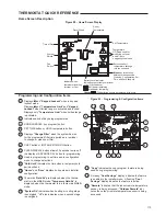
Страница 113: ...rmostat is in a temporary HOLD mode 10 Hours and Days displays during steps in installer configuration 9 Hold Until indicates the time when a temporary hold period will end 8 Used in programming to set time and in configuration menu to change selections 7 CLEAN DISPLAY button allows 30 seconds to wipe off the display or ADVANCE DAY button for programming 6 COPY button or INSTALLER CONFIG button 5 ...

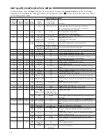
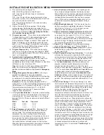
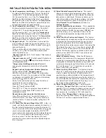
Страница 114: ...FF On Selects Automatic Schedule for comfort temperature Programming heat mode 18 16 AS Cool OFF On Selects Automatic Schedule for comfort temperature Programming cool mode 19 17 CS OFF 1 2 3 4 5 6 Selects Cool Saving Feature amount Cool Savings 20 18 HL Heat 99 62 98 TEMPERATURE LIMIT HEAT max heat set point 21 19 LL Cool 45 46 82 TEMPERATURE LIMIT COOL min cool set point 22 20 OFF L total P part...

Страница 115: ...ntinuously running during the periods of high demand Periods of high demand will normally occur during the late afternoon and early evening on the hottest days of the summer As demand lessens the adjustments to sensed temperature are reversed until sensed temperature returns to normal and CoolSavings no longer flashes 1 This control can be configured for MS2 Multi Sta ge System 2 heat 2 cool HP1 H...

Страница 116: ...nergize immediately With FA OFF second stage will not energize until the setpoint tempera ture is 1 F or more above actual temperature for more than ten minutes The Fast Cool feature FA Cool provides the same controls when the setpoint tempera ture is lowered INSTALLER CONFIGURATION MENU 25 Select Remote Temperature Sensor This control allows one wired remote temperature sensor indoor or outdoor b...

Страница 117: ...emperature or press Run Schedule to cancel HOLD and resume the programmed schedule Program Override Temporary Override Press or buttons to adjust the temperature This will override the temperature setting for a default four hour override period The override period can be shortened by pressing or lengthened by pressing Program Override period can range from 15 minutes to 7 days Example If you turn ...

Страница 118: ...he run mode for as long as the fan is in that position When FAN Prog position is selected and the system is in the Cool Heat or Auto mode the circulator blower fan will cycle ON for 10 minutes OFF for 20 minutes when the thermostat has not called for cooling or heating for the past 60 minutes To improve indoor air quality the system circulator can be programmed to run during any program time perio...

Страница 119: ...onday Saturday and Sunday If you are re programming a 5 1 1 day schedule pencil in your own times and temperatures directly below the factory times and temperatures If you are re programming a 7 day fill in all lines with the times and temperatures you want Keep the following guidelines in mind when planning your program In Heating lower temperatures will save energy In Cooling higher temperatures...

Страница 120: ...oggle the function and display from LS shown in actual temperature digits and On shown in clock digits to LS OFF to designate the local sensor is disabled The local sensor may be disabled only if the indoor remote sensor is enabled and functional If the indoor remote sensor is disabled or not functional the local sensor will automatically enable and display in the run schedule mode The actual temp...

Страница 121: ...lace door panel in proper position to engage safety interlock or door switch Tighten connections Re light pilot Many furnaces have safety devices that shut down when a lock out condition occurs If the heat works intermittently contact the furnace manufacturer or local HVAC service person for assistance Diagnostic Set SYSTEM Switch to HEAT and raise the setpoint above room temperature Within a few ...

Страница 122: ...l amount of insulation from the wire to expose clean new copper for the communicating con nections Fresh copper must be exposed when making the communi cating connections or communications may not be properly established Figures 96 through 97 below are wiring diagrams for connecting the furnace to an approved ClimateTalk communicat ing thermostat and approved Rheem or Ruud communicating condenser ...

Страница 123: ...stat will be communi cating with the furnace control and the furnace control will energize the con denser as necessary the additional relays have been added to the furnace control to allow this operation The thermostat connections labeled Y1 and Y2 on the I F C are normally inputs to the furnace control to turn on the blower when they are energized However in this configuration these normally inpu...

Страница 124: ...AULT area using a communicating thermostat see the installation and operation instructions for that thermo stat For detailed user menu text navigation and descriptions refer to the section of this manual titled COMMUNICATING SYSTEMS under the subsection titled USER MENUS Below describes some basic methods for entering and viewing furnace fault messages and user menus for two dif ferent communicati...

Страница 125: ... menu and subsequent sub menus with the HC TST501CMMS communicating thermo stat To get into the submenus use the up and down arrow keys of the thermo stat to display the desired menu and press the Installer Config button on the thermostat to enter that menu FIGURE 99 WIRING DIAGRAM COMMUNICATING CONFIGURATION ST A1118 01 4 ...

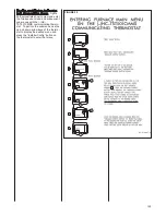
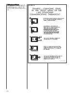
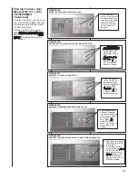
Страница 126: ...ER OF THE THERMOSTAT PRESS THE LEFT OR RIGHT ARROW KEY A UNTIL THE TEXT 15 IS DISPLAYED IN THE CORNER PRESS THE UP OR DOWN ARROW KEY OR THE MENU KEY TO SET THE VALUE IF THE MENU KEY IS PRESSED THE PREVIOUS MENU SCREEN WILL BE SHOWN BUT THE NEW VALUE 15 WILL BE SET AFTER ENTERING THE SETUP MENU OF THE FURNACE SEE STEP 7 IN FIGURE 99 THERE WILL BE SEVERAL VALUES THAT CAN BE CHANGED BY THE INSTALLER ...

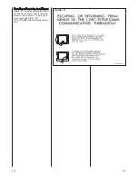
Страница 127: ...s Figure 101 below demonstrates how to escape from a menu back to the main screen or how to return to a previous menu level using the HC TST501CMMS communicating thermo stat FIGURE 101 WIRING DIAGRAM COMMUNICATING CONFIGURATION ST A1118 01 1 ...

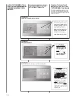
Страница 128: ...Furnace Fault Messages with the HC TST550CMMS Thermostat To enter a particular user menu on the HC TST550CMMS full color communicating thermostat follow the directions below FIGURE 102 ENTER THE ADVANCED INSTALLER MENUWIRING DIAGRAM COMMUNICATING CONFIGURATION FIGURE 103 SELECT FAULT STATUSIRING DIAGRAM COMMUNICATING CONFIGURATION 1 From the main screen press the left and right arrow keys together...

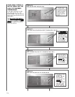
Страница 129: ...e next screen below will appear 4 The furnace menu options will appear Use the up and down arrow keys to select the desired menu Next press M to enter the desired menu Next the next screen below will appear FIGURE 109 NAVIGATE THE USER MENUS USING UP AND DOWN ARROW KEYS 5 Use the up and down arrow keys to view the menu items 6 To escape from this menu press the Enter to return to the fur nace user...

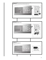
Страница 130: ...up user menus FIGURE 110 ENTER THE ADVANCED INSTALLER MENU 1 From the main screen press the left and right arrow keys together at the same time for at least 3 seconds The next screen below will appear 2 The ADVANCED INSTALLER MENU is displayed Use the up and down arrow keys to high light Communicating Devices Next press the M key The next screen below will appear 3 From the devices listed use the ...

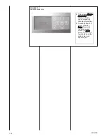
Страница 131: ...MAX HEAT Adj cur rently set to 0 FIGURE 115 SELECT THE DESIRED VALUE 7 6 Use the up and down arrow keys to view and navigate to the desired setup selection Once the desired menu item is highlighted press the M key to change the selec tion In this exam ple we will change the MAX HEAT Adj currently set to 0 to 7 FIGURE 116 UPDATING THE SUBSYSTEM 7 This screen Updating the Subsystem will be displayed...

Страница 132: ... screen Update Successful will be displayed briefly upon successfully changing the setting 9 To escape from this menu press the Enter to return to the furnace user menus or Home button or just wait a few minutes and the main screen will appear again ...

Отзывы: