55
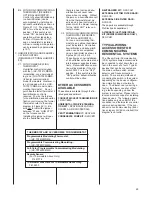
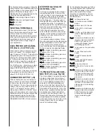
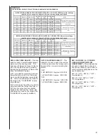
24 VAC THERMOSTAT
(TSTAT) INPUTS (J4 & J6)
24 VAC THERMOSTAT (TSTAT)
INPUTS (J4 & J6)
These connections are used with any
traditional 24VAC one-stage or two-
stage thermostat or the modulating,
non-communicating, thermostat speci-
fied for this modulating furnace. Fully
communicating thermostats must be
connected to the COMM NETWORK
CONNECTION (see section titled
COMMUNICATING SYSTEMS of this
document for details). Optimum heat-
ing performance will be realized only
with the fully modulating thermostat
(either communicating or non-commu-
nicating).
W1, Y1, Y2, G, C and R are the tradi-
tional thermostat inputs used in nearly
all HVAC equipment. Installation of the
thermostat to these connections is
straight-forward and simple.
HUM STAT – This terminal is used to
connect the output of a humidistat to
the furnace control to control humidifi-
cation and/or dehumidification.
Optional equipment is required for
these features. Please see the
section titled
HUMIDIFICTION AND
DEHUMIDIFICATION of this docu-
ment for more details.
V/W2 – This terminal is used to con-
nect the modulating signal (V) from
a non-communicating, fully modulat-
ing thermostat specified for use with
this furnace. It is used to transmit
the firing rate (determined by the
thermostat) to the furnace control.
In addition, a traditional 24VAC sig-
nal from a two-stage thermostat ter-
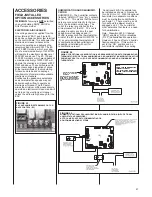
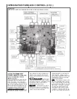
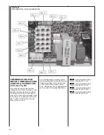
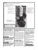
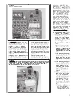
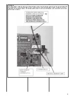
INTEGRATED FURNACE CONTROL (I.F.C.)
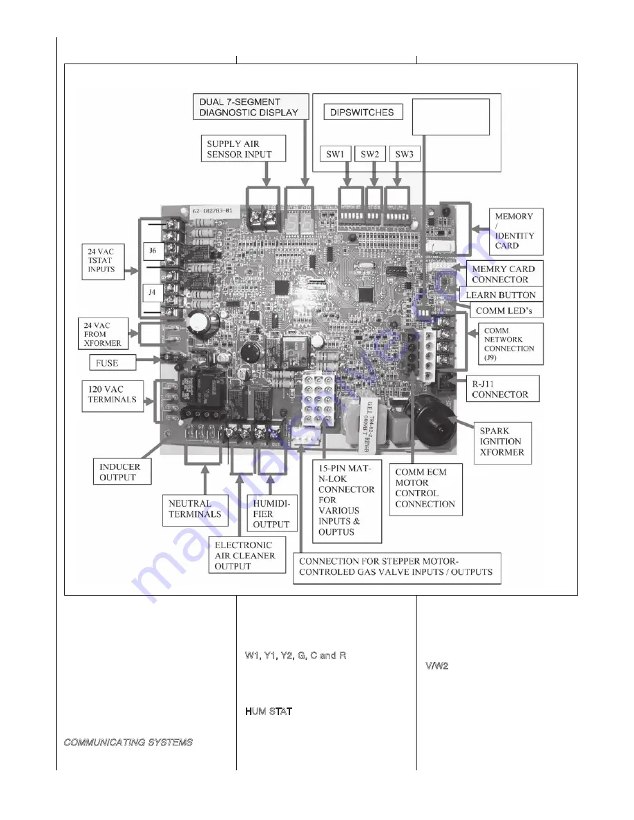
FIGURE 58
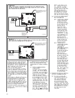
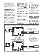
MODULATING CLIMATE-TALK COMMUNICATING FURNACE CONTROL (RHEEM # 62-102783-01)
BIAS/TERM
(COMM ONLY)
(all must be on)
Содержание RGFE
Страница 92: ...92 TABLE 21 FURNACE FAULT CODES EXPANDED W DESCRIPTIONS AND SOLUTIONS CONTINUED ...
Страница 93: ...93 TABLE 21 FURNACE FAULT CODES EXPANDED W DESCRIPTIONS AND SOLUTIONS CONTINUED ...
Страница 94: ...94 TABLE 21 FURNACE FAULT CODES EXPANDED W DESCRIPTIONS AND SOLUTIONS CONTINUED ...
Страница 95: ...95 TABLE 21 FURNACE FAULT CODES EXPANDED W DESCRIPTIONS AND SOLUTIONS CONTINUED ...
Страница 96: ...96 TABLE 21 FURNACE FAULT CODES EXPANDED W DESCRIPTIONS AND SOLUTIONS CONTINUED ...
Страница 97: ...97 TABLE 21 FURNACE FAULT CODES EXPANDED W DESCRIPTIONS AND SOLUTIONS CONTINUED ...
Страница 98: ...98 TABLE 21 FURNACE FAULT CODES EXPANDED W DESCRIPTIONS AND SOLUTIONS CONTINUED ...
Страница 99: ...99 TABLE 21 FURNACE FAULT CODES EXPANDED W DESCRIPTIONS AND SOLUTIONS CONTINUED ...
Страница 101: ...101 TABLE 21 FURNACE FAULT CODES EXPANDED W DESCRIPTIONS AND SOLUTIONS CONTINUED when the inducer is energized at low ...
Страница 102: ...102 TABLE 21 FURNACE FAULT CODES EXPANDED W DESCRIPTIONS AND SOLUTIONS CONTINUED ...
Страница 103: ...103 TABLE 21 FURNACE FAULT CODES EXPANDED W DESCRIPTIONS AND SOLUTIONS CONTINUED ...
Страница 104: ...104 TABLE 21 FURNACE FAULT CODES EXPANDED W DESCRIPTIONS AND SOLUTIONS CONTINUED ...
Страница 105: ...105 TABLE 21 FURNACE FAULT CODES EXPANDED W DESCRIPTIONS AND SOLUTIONS CONTINUED ...
Страница 106: ...106 FIGURE 83 WIRING DIAGRAM STEPPER MODULATING GAS VALVE FUEL CODE HA OR HB FURNACE MODEL IS RGFE RGGE ...
Страница 107: ...107 FIGURE 84 WIRING DIAGRAM SOLENOID CONTROLLED GAS VALVE FUEL CODE HG OR HH FURNACE MODEL RGGE RGFE RGJF ...

