61
will not operate the furnace until fur-
nace shared data is loaded in the
field either via the original memory
card or via redundant copies stored
on various components in a commu-
nicating network (the latter applies
only to installations configured as
communicating systems and NOT to
so-called legacy (24VAC) controlled
systems).
When the furnace control is
replaced, the original memory card
must be broken away from the origi-
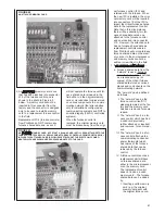
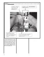
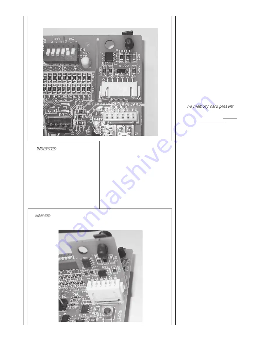
2. An INSERTED memory card is one
that has been inserted into connector
J15 of the furnace control and is
shown in the photo in Figure 63
below. A memory card will not be
inserted in this connector from the
factory and the connector is designed
only to be used to install a memory
card to a replacement furnace control
in the field.
Replacement IFC’s (furnace controls)
from ProStock do NOT contain any
furnace shared data and, as such,
nal furnace control (IFC) and
retained with the furnace. When
the new IFC is installed, the origi-
nal memory card will be inserted
into connector J15 of the IFC to
impart the critical furnace shared
data to the replacement control.
Note that in this circumstance
there will be essentially two fur-
nace shared data cards; one
attached to the furnace control
and one inserted into connector
J15. However, the attached card
has no furnace shared data as
replacement controls ordered
from ProStock will not contain any
furnace shared data on the mem-
ory card or in the microprocessor
and memory cards cannot be
written (or rewritten) in the field.
1. If no memory card present, –
a. Furnace shared data from the
“network” is used. Furnace
network shared data is defined
as a redundant copy (or
copies) of the critical furnace
shared data stored at various
places and components on the
communicating network.
The “network” can be defined
as follows:
I. The “network” can be the
furnace control itself if it
was programmed at the fac-
tory and the memory card
has been removed for some
reason.
II. The “network” can be a fur-
nace control which has had
a valid card previously
(either attached or inserted)
and removed for some rea-
son.
III. The “network” can be a fur-
nace control attached to a
communicating condenser
and/or thermostat which
has copies of the furnace
shared data that can be
retrieved by the furnace
control.
IV. A furnace control sent as a
replacement part will have
no furnace shared data
either in the microprocessor
or on the memory card.
The replacement control
does not include a valid
memory card. The furnace
shared data can be added
by:
1. Inserting a valid memory
card (e.g. the original
memory card sent with
the original furnace con-
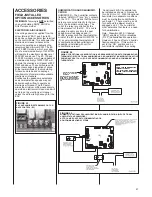
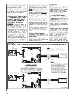
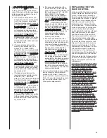
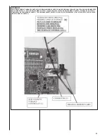
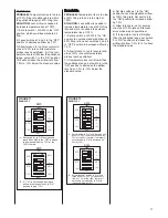
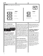
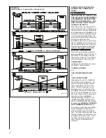
FIGURE 62
AN ATTACHED MEMORY CARD
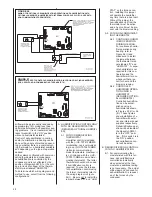
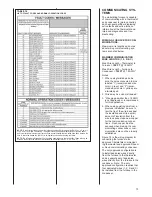
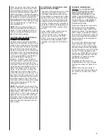
FIGURE 63
AN INSERTED MEMORY CARD. NOTE THAT A BLANK CARD IS STILL SEEN ATTACHED TO THE
FURNACE CONTROL BELOW. REPLACEMENT FURNACE CONTROLS FROM PROSTOCK WILL
INCLUDE THIS ATTACHED CARD (BELOW) EXCEPT WITHOUT THE ELECTRONIC COMPO-
NENTS WHICH ARE SHOWN HERE SURFACE-MOUNTED TO THE CARD.
Содержание RGFE
Страница 92: ...92 TABLE 21 FURNACE FAULT CODES EXPANDED W DESCRIPTIONS AND SOLUTIONS CONTINUED ...
Страница 93: ...93 TABLE 21 FURNACE FAULT CODES EXPANDED W DESCRIPTIONS AND SOLUTIONS CONTINUED ...
Страница 94: ...94 TABLE 21 FURNACE FAULT CODES EXPANDED W DESCRIPTIONS AND SOLUTIONS CONTINUED ...
Страница 95: ...95 TABLE 21 FURNACE FAULT CODES EXPANDED W DESCRIPTIONS AND SOLUTIONS CONTINUED ...
Страница 96: ...96 TABLE 21 FURNACE FAULT CODES EXPANDED W DESCRIPTIONS AND SOLUTIONS CONTINUED ...
Страница 97: ...97 TABLE 21 FURNACE FAULT CODES EXPANDED W DESCRIPTIONS AND SOLUTIONS CONTINUED ...
Страница 98: ...98 TABLE 21 FURNACE FAULT CODES EXPANDED W DESCRIPTIONS AND SOLUTIONS CONTINUED ...
Страница 99: ...99 TABLE 21 FURNACE FAULT CODES EXPANDED W DESCRIPTIONS AND SOLUTIONS CONTINUED ...
Страница 101: ...101 TABLE 21 FURNACE FAULT CODES EXPANDED W DESCRIPTIONS AND SOLUTIONS CONTINUED when the inducer is energized at low ...
Страница 102: ...102 TABLE 21 FURNACE FAULT CODES EXPANDED W DESCRIPTIONS AND SOLUTIONS CONTINUED ...
Страница 103: ...103 TABLE 21 FURNACE FAULT CODES EXPANDED W DESCRIPTIONS AND SOLUTIONS CONTINUED ...
Страница 104: ...104 TABLE 21 FURNACE FAULT CODES EXPANDED W DESCRIPTIONS AND SOLUTIONS CONTINUED ...
Страница 105: ...105 TABLE 21 FURNACE FAULT CODES EXPANDED W DESCRIPTIONS AND SOLUTIONS CONTINUED ...
Страница 106: ...106 FIGURE 83 WIRING DIAGRAM STEPPER MODULATING GAS VALVE FUEL CODE HA OR HB FURNACE MODEL IS RGFE RGGE ...
Страница 107: ...107 FIGURE 84 WIRING DIAGRAM SOLENOID CONTROLLED GAS VALVE FUEL CODE HG OR HH FURNACE MODEL RGGE RGFE RGJF ...

