79
When faults are cleared, the right
seven segment display on the furnace
control will flash the upper and lower
horizontal bars once.
Note that the “FAULT HISTORY” only
accumulates days when power is
applied to the furnace control board.
For example, if a fault actually occurred
ten days ago and the furnace was not
powered for two of the ten days, the
fault will be displayed with the text
“DAYS 8” instead of “DAYS 10” is dis-
played to indicate the number of days
since the fault occurred.
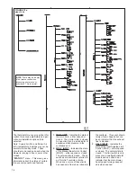
“UNIT INFO” menu – This menu gives
information about the furnace.
1. MODEL NUMBER (MN)
2. SERIAL NUMBER (SN)
3. SOFTWARE VERS.
“SETUP” menu – This menu permits
the field adjustment of certain parame-
ters of the furnace. The selected val-
ues will be saved in memory even
when power is lost and restored. The
procedure for making changes in the
furnace setup menu will vary depend-
ing on the thermostat or service tool
that is used. To enter, navigate, make
changes to or exit the furnace “SETUP”
menu using a communicating thermo-
stat, see the installation and operation
instructions for that thermostat.
1. HEAT RISE ADJ* – The value of
the heat rise can be changed to
reflect the comfort of the homeown-
er. The value can be changed
between “NOM +10” (nominal or
mid temperature rise plus 10
degrees F) and “NOM” (nominal or
mid temperature rise). Additional
adjustment can be to low and high
heating rates (and all points
between) at the “MIN HEAT ADJ”
and “MAX HEAT ADJ” menu items
in items 2 and 3 below.
The temperature rise values listed
are for reference only. The actual
measured temperature rise may be
different than expected by several
degrees.
The default factory setting for the
heat rise is “NOM +10”.
*ALL TEMPERATURES CAN BE
DISPLAYED ONLY IN FAHREN-
HEIT VALUES
2. MIN HEAT ADJ - This selection
permits the adjustment of the low
heat airflow. Operation of this
selection is exactly as with the dip-
switches at SW3 at the furnace
control. The low heat rise can be
changed by increasing or decreas-
ing the airflow slightly. Adjustments
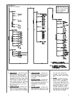
“LIFE HIST” menu – This menu gives
information about the number of cycles
and the amount of time spent in various
modes of operation over the life of the
furnace.
NOTE:
For both 2 WK & LIFE HIST., the
value saved prior to power loss may not
include information from the last hour of
operation. This is because the informa-
tion is only stored once every hour.
1. TOTAL DAYS PWRD – Indicates
the total number of days that the
furnace has been powered. This
number is not affected by any ther-
mostat operation.
2. MOD HT HRS – Indicates the num-
ber of hours of operation of gas
heating operation over the life of the
furnace.
3. MOD HT CYCLS – Indicates the
number of cycles of operation (i.e.:
the number of times it turned on and
off) of gas heat operation over the
life of the furnace.
4. BLOWER HRS – Indicates the
number of hours of continuous fan
operation over the life of the fur-
nace.
5. BLOWER CYCLS – Indicates the
number of cycles of operation (i.e.:
the number of times it turned on and
off) of the continuous fan operation
over the life of the furnace.
“FAULT HISTORY” menu – This menu
gives information about the six most
recent faults experienced by the fur-
nace. The most recent fault is dis-
played upon entering the menu. Three
seconds later the text “DAYS“ is dis-
played followed by a number. The num-
ber indicates the number of days since
that fault was experienced.
The faults can be viewed in order of
occurrence. Pressing the down arrow
key once will permit viewing o
f the next
most recent fault. Pressing the key
again will display the second most
recent fault and so on.
If no fault present in the memory, the
text “NO FAULT” and “DAYS 0” will be
displayed. It is possible that there will
be less than six faults stored (if less
than six faults have occurred since
installation or clearing of faults). In this
case, the existing faults will be dis-
played in the order of occurrence and
the remaining faults will be displayed as
“NO FAULT” and “DAYS 0”.
The final item in this menu is “CLEAR
FAULTS”. The options are “yES” and
“no”. This item permits the faults to be
cleared so all six positions will display
“NO FAULT” and “DAYS 0”.
are -15%, -7.5%, 0, +7.5% and
+15%. Note that when a low
heat adjustment is made, the
low heat rate is adjusted and all
points between low and high
heat will be adjusted proportion-
ally with the greatest adjustment
on the low end and the least
adjustment on the high end.
IMPORTANT: Note that increas-
ing the airflow will decrease the
temperature rise and decreasing
the airflow will increase the tem-
perature rise. This may not be
obvious at first.
The default factory setting for
the min heat adjustment is “0”.
3. MAX HEAT ADJ - This selection
permits the adjustment of the
high heat airflow. Operation of
this selection is exactly as with
the dipswitches at SW3 at the
furnace control. The high heat
rise can be changed by increas-
ing or decreasing the airflow
slightly. Adjustments are -15%, -
7.5%, 0, +7.5% and +15%.
Note that when a high heat
adjustment is made, the high
heat rate is adjusted and all
points between high and low
heat w
ill be adjusted proportion-
ally with the greatest adjustment
on the high end and the least
adjustment on the low end.
IMPORTANT: Note that increas-
ing the airflow will decrease the
temperature rise and decreasing
the airflow will increase the tem-
perature rise. This may not be
obvious at first.
The default factory setting for
the max heat adjustment is “0”.
4. SUPPLY AIR SENS – This
selection permits the disabling
and enabling of the supply air
sensor input. In many cases, it
may not be possible to install
this sensor. When this is the
case, the selection can be
changed to “OFF”. Selecting
“on” or “OFF” will affect how the
“TEMP RISE” (TEMPerature
RISE) and “SUPPLY TEMP” val-
ues are displayed in the “STA-
TUS 2” menu. See the descrip-
tions for these items in the
“STATUS 2” menu descriptions
above for more information.
Note that turning this selection
to “OFF” will prevent the “82”
fault code (SA SENSOR FLT)
from being displayed on power-
up (or at any other time) and
from logging in the fault buffer.
The default factory setting for
the supply air sensor input is
“on”.
Содержание RGFE
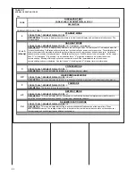
Страница 92: ...92 TABLE 21 FURNACE FAULT CODES EXPANDED W DESCRIPTIONS AND SOLUTIONS CONTINUED ...
Страница 93: ...93 TABLE 21 FURNACE FAULT CODES EXPANDED W DESCRIPTIONS AND SOLUTIONS CONTINUED ...
Страница 94: ...94 TABLE 21 FURNACE FAULT CODES EXPANDED W DESCRIPTIONS AND SOLUTIONS CONTINUED ...
Страница 95: ...95 TABLE 21 FURNACE FAULT CODES EXPANDED W DESCRIPTIONS AND SOLUTIONS CONTINUED ...
Страница 96: ...96 TABLE 21 FURNACE FAULT CODES EXPANDED W DESCRIPTIONS AND SOLUTIONS CONTINUED ...
Страница 97: ...97 TABLE 21 FURNACE FAULT CODES EXPANDED W DESCRIPTIONS AND SOLUTIONS CONTINUED ...
Страница 98: ...98 TABLE 21 FURNACE FAULT CODES EXPANDED W DESCRIPTIONS AND SOLUTIONS CONTINUED ...
Страница 99: ...99 TABLE 21 FURNACE FAULT CODES EXPANDED W DESCRIPTIONS AND SOLUTIONS CONTINUED ...
Страница 101: ...101 TABLE 21 FURNACE FAULT CODES EXPANDED W DESCRIPTIONS AND SOLUTIONS CONTINUED when the inducer is energized at low ...
Страница 102: ...102 TABLE 21 FURNACE FAULT CODES EXPANDED W DESCRIPTIONS AND SOLUTIONS CONTINUED ...
Страница 103: ...103 TABLE 21 FURNACE FAULT CODES EXPANDED W DESCRIPTIONS AND SOLUTIONS CONTINUED ...
Страница 104: ...104 TABLE 21 FURNACE FAULT CODES EXPANDED W DESCRIPTIONS AND SOLUTIONS CONTINUED ...
Страница 105: ...105 TABLE 21 FURNACE FAULT CODES EXPANDED W DESCRIPTIONS AND SOLUTIONS CONTINUED ...
Страница 106: ...106 FIGURE 83 WIRING DIAGRAM STEPPER MODULATING GAS VALVE FUEL CODE HA OR HB FURNACE MODEL IS RGFE RGGE ...
Страница 107: ...107 FIGURE 84 WIRING DIAGRAM SOLENOID CONTROLLED GAS VALVE FUEL CODE HG OR HH FURNACE MODEL RGGE RGFE RGJF ...

