89
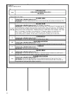
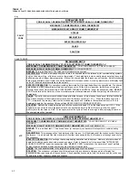
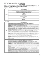
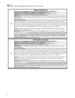
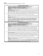
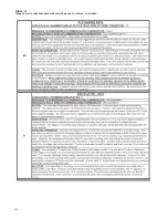
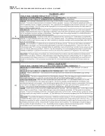
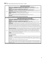
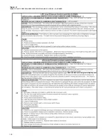
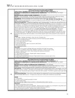
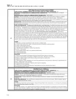
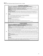
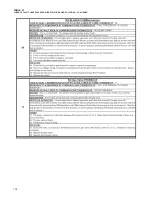
TABLE 20
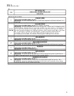
NORMAL OPERATION CODES
Key
NORMAL OPERATION CODES
NORMAL OPERATION CODES
CODE AT DUAL 7-SEGMENT DISPLAY OF IFC:
0
CODE AT DUAL 7-SEGMENT DISPLAY OF IFC:
H or h
(steady on - not blinking)
Cd
DEHUMIDIFICATION MODE
CODE AT DUAL 7-SEGMENT DISPLAY OF IFC:
Cd
DESCRIPTION:
This code indicates that cooling is active with dehumidification active at the same time. When
dehumidification is active, the cooling airflow will be reduced in order to allow water to accumulate on the condenser
thereby removing humidity from the conditioned environment.
CODE AT DUAL 7-SEGMENT DISPLAY OF IFC:
F
C
COOLING MODE
DESCRIPTION:
This code indicates the furnade is in cooling mode (any stage).
GAS HEAT MODE
F
FAN MODE
DESCRIPTION:
The furnace is in continous fan mode.
HP
HEAT PUMP HEAT MODE
DESCRIPTION:
This code indicates the furnade is in heat-pump heating mode (dual-fuel systems only) (any stage).
CODE AT DUAL 7-SEGMENT DISPLAY OF IFC:
HP
or hP
CODE
STANDBY MODE
DESCRIPTION:
This code is displayed anytime there is no fault code to display and no thermostat call present. The
furnace is idle.
CODE AT DUAL 7-SEGMENT DISPLAY OF IFC:
C
DISPLAYED TEXT
0
H or h
(steady)
DESCRIPTION:
This code indicates that the heat-pump is in deFrost mode (dual-fuel systems only) and furnace is
operating as supplemental heat at a fixed 65% of maximum gas heating capacity.
dF
DEFROST MODE
CODE AT DUAL 7-SEGMENT DISPLAY OF IFC:
dF
DESCRIPTION
DESCRIPTION:
This code is displayed any time there is a call for gas heat. The lower-case "h" is displayed when the
furnace is calibrating. Calibration will occur during the first heat call after power reset or power-up. The calibration cycle
allows the blower to be adjusted to deliver the proper airflow amount for a given heat rise at a given rate. Calibration
takes more five minutes at a reduced input. Calibration will not occur if the SA sensor is not connected. If either (upper
case "H" or lower-case "h" is blinking, it is an indication that a "V" signal is not present on a system that is non-
communicating. Blinking of this code will not be considered a fault if the thermostat chosen for use is non-
communicating and non-modulating. See fault codes "H" (blinking) and "h" (blinking) for more information.
CODE AT DUAL 7-SEGMENT DISPLAY OF IFC
Содержание RGFE
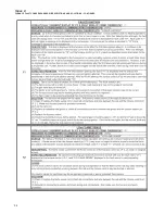
Страница 92: ...92 TABLE 21 FURNACE FAULT CODES EXPANDED W DESCRIPTIONS AND SOLUTIONS CONTINUED ...
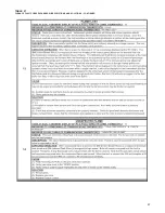
Страница 93: ...93 TABLE 21 FURNACE FAULT CODES EXPANDED W DESCRIPTIONS AND SOLUTIONS CONTINUED ...
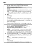
Страница 94: ...94 TABLE 21 FURNACE FAULT CODES EXPANDED W DESCRIPTIONS AND SOLUTIONS CONTINUED ...
Страница 95: ...95 TABLE 21 FURNACE FAULT CODES EXPANDED W DESCRIPTIONS AND SOLUTIONS CONTINUED ...
Страница 96: ...96 TABLE 21 FURNACE FAULT CODES EXPANDED W DESCRIPTIONS AND SOLUTIONS CONTINUED ...
Страница 97: ...97 TABLE 21 FURNACE FAULT CODES EXPANDED W DESCRIPTIONS AND SOLUTIONS CONTINUED ...
Страница 98: ...98 TABLE 21 FURNACE FAULT CODES EXPANDED W DESCRIPTIONS AND SOLUTIONS CONTINUED ...
Страница 99: ...99 TABLE 21 FURNACE FAULT CODES EXPANDED W DESCRIPTIONS AND SOLUTIONS CONTINUED ...
Страница 101: ...101 TABLE 21 FURNACE FAULT CODES EXPANDED W DESCRIPTIONS AND SOLUTIONS CONTINUED when the inducer is energized at low ...
Страница 102: ...102 TABLE 21 FURNACE FAULT CODES EXPANDED W DESCRIPTIONS AND SOLUTIONS CONTINUED ...
Страница 103: ...103 TABLE 21 FURNACE FAULT CODES EXPANDED W DESCRIPTIONS AND SOLUTIONS CONTINUED ...
Страница 104: ...104 TABLE 21 FURNACE FAULT CODES EXPANDED W DESCRIPTIONS AND SOLUTIONS CONTINUED ...
Страница 105: ...105 TABLE 21 FURNACE FAULT CODES EXPANDED W DESCRIPTIONS AND SOLUTIONS CONTINUED ...
Страница 106: ...106 FIGURE 83 WIRING DIAGRAM STEPPER MODULATING GAS VALVE FUEL CODE HA OR HB FURNACE MODEL IS RGFE RGGE ...
Страница 107: ...107 FIGURE 84 WIRING DIAGRAM SOLENOID CONTROLLED GAS VALVE FUEL CODE HG OR HH FURNACE MODEL RGGE RGFE RGJF ...

