tions are available from: “National
Fire Protection Association, Inc.,
Batterymarch Park, Quincy, MA
02269.” These publications are:
• ANSI/NFPA No. 70-(Latest Edition)
National Electrical Code.
• NFPA90A Installation of Air
Conditioning and Ventilating
Systems.
• NFPA90B Installation of warm air
heating and air conditioning sys-
tems.
• The equipment has been evaluat-
ed in accordance with the Code of
Federal Regulations, Chapter XX,
Part 3280.
IMPORTANT INFORMA-
TION ABOUT EFFICIENCY
AND INDOOR AIR
QUALITY
Central cooling and heating equip-
ment is only as efficient as the duct
system that carries the cooled or
heated air. To maintain efficiency,
comfort and good indoor air quality, it
is important to have the proper bal-
ance between the air being supplied
to each room and the air returning to
the cooling and heating equipment.
Proper balance and sealing of the
duct system improves the efficiency
of the heating and air conditioning
system and improves the indoor air
quality of the home by reducing the
amount of airborne pollutants that
enter homes from spaces where the
ductwork and / or equipment is locat-
ed. The manufacturer and the U.S.
Environmental Protection Agency’s
Energy Star Program recommend
that central duct systems be checked
by a qualified contractor for proper
balance and sealing.
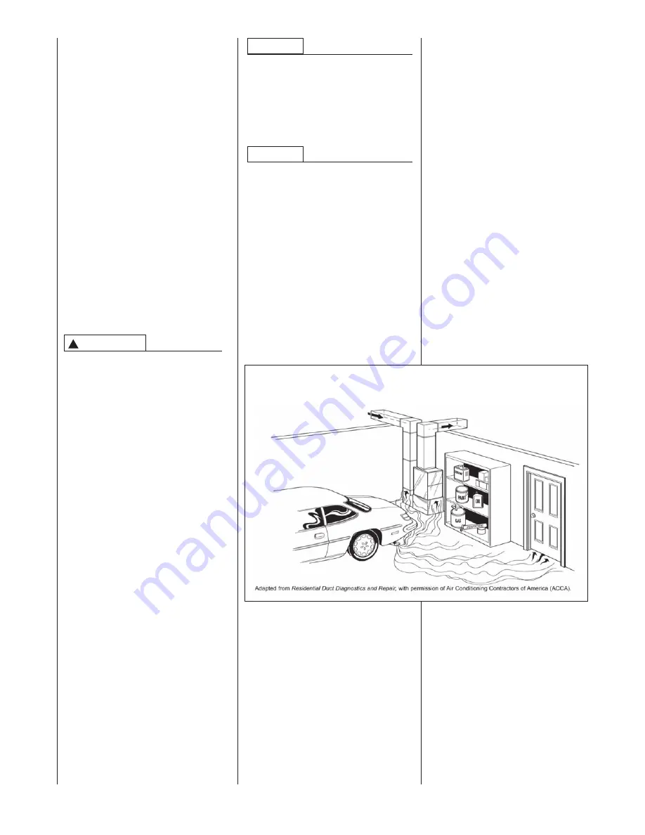
DUCT LEAKS CAN CREATE AN
UNBALANCED SYSTEM AND
DRAW POLLUTANTS SUCH AS
DIRT, DUST, FUMES AND ODORS
INTO THE HOME CAUSING PROP-
ERTY DAMAGE. FUMES AND
ODORS FROM TOXIC, VOLATILE
OR FLAMMABLE CHEMICALS, AS
WELL AS AUTOMOBILE EXHAUST
AND CARBON MONOXIDE (CO),
CAN BE DRAWN INTO THE LIVING
SPACE THROUGH LEAKING
DUCTS AND UNBALANCED DUCT
SYSTEMS CAUSING PERSONAL
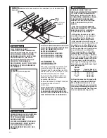
INJURY OR DEATH (SEE FIGURE
4).
• IF AIR-MOVING EQUIPMENT OR
DUCTWORK IS LOCATED IN
GARAGES OR OFF-GARAGE
STORAGE AREAS - ALL JOINTS,
SEAMS, AND OPENINGS IN THE
EQUIPMENT AND DUCT MUST
BE SEALED TO LIMIT THE
MIGRATION OF TOXIC FUMES
AND ODORS INCLUDING CAR-
BON MONOXIDE FROM MIGRAT-
ING INTO THE LIVING SPACE.
• IF AIR-MOVING EQUIPMENT OR
DUCTWORK IS LOCATED IN
SPACES CONTAINING FUEL
BURNING APPLIANCES SUCH
AS WATER HEATERS OR BOIL-
ERS - ALL JOINTS, SEAMS, AND
OPENINGS IN THE EQUIPMENT
AND DUCT MUST ALSO BE
SEALED TO PREVENT DEPRES-
SURIZATION OF THE SPACE
AND POSSIBLE MIGRATION OF
COMBUSTION BYPRODUCTS
INCLUDING CARBON MONOX-
IDE INTO THE LIVING SPACE.
IMPROPER INSTALLATION, OR
INSTALLATION NOT MADE IN
ACCORDANCE WITH THE CSA
INTERNATIONAL (CSA) CERTIFICA-
TION OR THESE INSTRUCTIONS,
CAN RESULT IN UNSATISFACTORY
OPERATION AND/OR DANGEROUS
CONDI-TIONS AND ARE NOT COV-
ERED BY THE UNIT WARRANTY.
IN COMPLIANCE WITH RECOG-
NIZED CODES, IT IS RECOMMEND-
ED THAT AN AUXILIARY DRAIN PAN
BE INSTALLED UNDER ALL EVAPO-
RATOR COILS OR UNITS CONTAIN-
ING EVAPORATOR COILS THAT ARE
LOCATED IN ANY AREA OF A
STRUCTURE WHERE DAMAGE TO
THE BUILDING OR BUILDING CON-
TENTS MAY OCCUR AS A RESULT
OF AN OVERFLOW OF THE COIL
DRAIN PAN OR A STOPPAGE IN THE
PRIMARY CONDENSATE DRAIN PIP-
ING. SEE ACCESSORIES SECTION
OF THESE INSTRUCTIONS FOR
AUXILIARY HORIZONTAL OVER-
FLOW PAN INFORMATION (MODEL
RXBM).
matches what is required for the
job specification.
• Read the entire instructions before
starting the installation.
• Some building codes require extra
cabinet insulation and gasketing
when unit is installed in attic appli-
cations.
• If
installed in an unconditioned
space, apply caulking around the
power wires, control wires, refriger-
ant tubing and condensate line
where they enter the cabinet. Seal
the power wires on the inside
where they exit conduit opening.
Caulking is required to prevent air
leakage into and condensate from
forming inside the unit, control box,
and on electrical controls.
• Install the unit in such a way as to
allow necessary access to the
coil/filter rack and blower/control
compartment.
• Install the unit in a level position to
ensure proper condensate
drainage. Make sure unit is level in
both directions within 1/8”.
• Install the unit in accordance with
any local code which may apply
and the national codes. Latest edi-
RECEIVING
Immediately upon receipt, all cartons
and contents should be inspected for
transit damage. Units with damaged
cartons should be opened immedi-
ately. If damage is found, it should
be noted on the delivery papers, and
a damage claim filed with the last
carrier.
• After unit has been delivered to
job site, remove carton taking care
not to damage unit.
• Check the unit rating plate for unit
size, electric heat, coil, voltage,
phase, etc. to be sure equipment
NOTICE
NOTICE
!
WARNING
FIGURE 4
MIGRATION OF DANGEROUS SUBSTANCES, FUMES, AND ODORS INTO LIVING SPACES
8
Содержание RGFE
Страница 92: ...92 TABLE 21 FURNACE FAULT CODES EXPANDED W DESCRIPTIONS AND SOLUTIONS CONTINUED ...
Страница 93: ...93 TABLE 21 FURNACE FAULT CODES EXPANDED W DESCRIPTIONS AND SOLUTIONS CONTINUED ...
Страница 94: ...94 TABLE 21 FURNACE FAULT CODES EXPANDED W DESCRIPTIONS AND SOLUTIONS CONTINUED ...
Страница 95: ...95 TABLE 21 FURNACE FAULT CODES EXPANDED W DESCRIPTIONS AND SOLUTIONS CONTINUED ...
Страница 96: ...96 TABLE 21 FURNACE FAULT CODES EXPANDED W DESCRIPTIONS AND SOLUTIONS CONTINUED ...
Страница 97: ...97 TABLE 21 FURNACE FAULT CODES EXPANDED W DESCRIPTIONS AND SOLUTIONS CONTINUED ...
Страница 98: ...98 TABLE 21 FURNACE FAULT CODES EXPANDED W DESCRIPTIONS AND SOLUTIONS CONTINUED ...
Страница 99: ...99 TABLE 21 FURNACE FAULT CODES EXPANDED W DESCRIPTIONS AND SOLUTIONS CONTINUED ...
Страница 101: ...101 TABLE 21 FURNACE FAULT CODES EXPANDED W DESCRIPTIONS AND SOLUTIONS CONTINUED when the inducer is energized at low ...
Страница 102: ...102 TABLE 21 FURNACE FAULT CODES EXPANDED W DESCRIPTIONS AND SOLUTIONS CONTINUED ...
Страница 103: ...103 TABLE 21 FURNACE FAULT CODES EXPANDED W DESCRIPTIONS AND SOLUTIONS CONTINUED ...
Страница 104: ...104 TABLE 21 FURNACE FAULT CODES EXPANDED W DESCRIPTIONS AND SOLUTIONS CONTINUED ...
Страница 105: ...105 TABLE 21 FURNACE FAULT CODES EXPANDED W DESCRIPTIONS AND SOLUTIONS CONTINUED ...
Страница 106: ...106 FIGURE 83 WIRING DIAGRAM STEPPER MODULATING GAS VALVE FUEL CODE HA OR HB FURNACE MODEL IS RGFE RGGE ...
Страница 107: ...107 FIGURE 84 WIRING DIAGRAM SOLENOID CONTROLLED GAS VALVE FUEL CODE HG OR HH FURNACE MODEL RGGE RGFE RGJF ...


