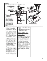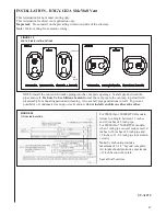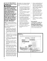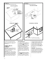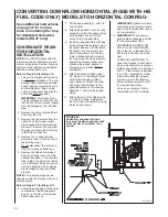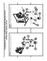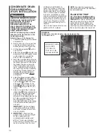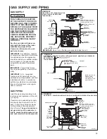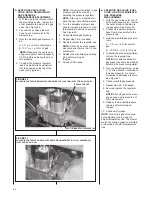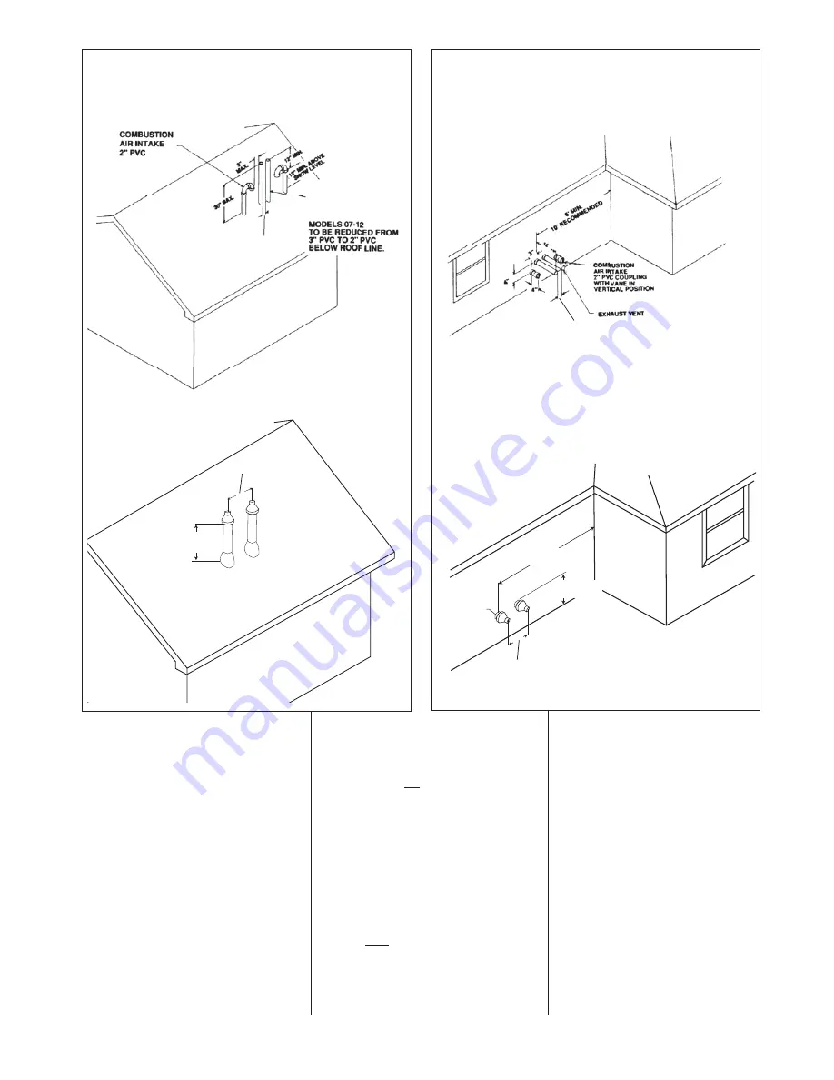
FIGURE 26
TWO FURNACE VENTING THROUGH WALL
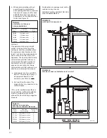
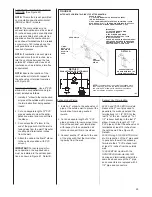
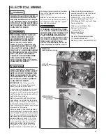
FIGURE 25
TWO FURNACE VENTING THROUGH ROOF
more than two furnaces are to be
vented, there must be at least 4 feet
between the first two furnaces and
the third, etc.
CONNECTING TO
FURNACE
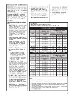
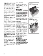
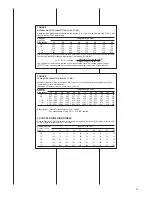
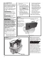
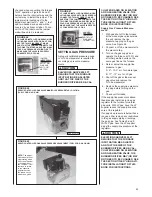
IMPORTANT:
Clean and deburr all
pipe cuts. The shavings must not be
allowed to block the exhaust, inlet or
condensate drain pipes.
IMPORTANT:
When indoor combus-
tion air is used, the inlet air opening
at the furnace must be protected from
accidental blockage. On downflow
models, install a double elbow in the
top inlet air opening. See Figure 30.
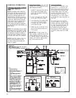
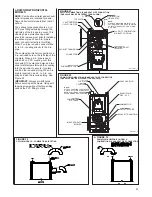
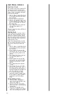
UPFLOW MODELS
The exhaust air pipe connection is a
2-in. female PVC pipe fitting extend-
ing through the left side of the fur-
nace top plate. See Figure 27. This
opening has a protective cap which
should be removed just prior to
installing the exhaust pipe. When 2-
in. pipe is used, connect it directly to
this fitting. When 3-in. pipe is used,
connect a 2 to 3-in. coupling to this
fitting with a short piece of 2-in. PVC
pipe.
The inlet combustion air connection
is at the right side of the top plate.
An alternate combustion inlet air con-
nection may be made on the right
side of the jacket. The alternate con-
EXHAUST VENT
MODELS 06-07
TO BE REDUCED TO
1-1/2” PVC LAST 12”.
3” MININUM
24” MAXIMUM
nection opening has a plastic cap. A
combustion inlet air connection fitting
is supplied with the furnace and it
must be installed in the furnace by
screwing it into the opening. Make
sure the rubber “O-ring” supplied with
the furnace is used with this fitting.
See Figure 27.
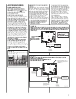
IMPORTANT:
When using indoor
combustion air, the furnace air open-
ing must be protected from accidental
blockage. Install a 2-inch 90° elbow
pointing downward on the side or a
double elbow pointing downward in
the top opening. See Figure 28.
TWO-PIPE VENTING
CONCENTRIC VENTING
8"
MINIMUM 12" ABOVE AVERAGE
SNOW ACCUMULATION. MAXIMUM
OF 24 IN. ABOVE ROOF.
SEE CONCENTRIC
VENT SECTION
ON PAGE 23
FOR MORE
INFORMATION.
TWO-PIPE VENTING
CONCENTRIC VENTING
8"
MAXIMUM 1"
DISTANCE
FROM WALL
MINIMUM 12"
ABOVE GRADE
6' MINIMUM
10' RECOMMENDED
SEE CONCENTRIC VENT SECTION
ON PAGE 23 FOR MORE INFORMATION.
3” MININUM
24” MAXIMUM
8” MININUM
24” MAXIMUM
8” MININUM
24” MAXIMUM
32
Содержание RGFE
Страница 92: ...92 TABLE 21 FURNACE FAULT CODES EXPANDED W DESCRIPTIONS AND SOLUTIONS CONTINUED ...
Страница 93: ...93 TABLE 21 FURNACE FAULT CODES EXPANDED W DESCRIPTIONS AND SOLUTIONS CONTINUED ...
Страница 94: ...94 TABLE 21 FURNACE FAULT CODES EXPANDED W DESCRIPTIONS AND SOLUTIONS CONTINUED ...
Страница 95: ...95 TABLE 21 FURNACE FAULT CODES EXPANDED W DESCRIPTIONS AND SOLUTIONS CONTINUED ...
Страница 96: ...96 TABLE 21 FURNACE FAULT CODES EXPANDED W DESCRIPTIONS AND SOLUTIONS CONTINUED ...
Страница 97: ...97 TABLE 21 FURNACE FAULT CODES EXPANDED W DESCRIPTIONS AND SOLUTIONS CONTINUED ...
Страница 98: ...98 TABLE 21 FURNACE FAULT CODES EXPANDED W DESCRIPTIONS AND SOLUTIONS CONTINUED ...
Страница 99: ...99 TABLE 21 FURNACE FAULT CODES EXPANDED W DESCRIPTIONS AND SOLUTIONS CONTINUED ...
Страница 101: ...101 TABLE 21 FURNACE FAULT CODES EXPANDED W DESCRIPTIONS AND SOLUTIONS CONTINUED when the inducer is energized at low ...
Страница 102: ...102 TABLE 21 FURNACE FAULT CODES EXPANDED W DESCRIPTIONS AND SOLUTIONS CONTINUED ...
Страница 103: ...103 TABLE 21 FURNACE FAULT CODES EXPANDED W DESCRIPTIONS AND SOLUTIONS CONTINUED ...
Страница 104: ...104 TABLE 21 FURNACE FAULT CODES EXPANDED W DESCRIPTIONS AND SOLUTIONS CONTINUED ...
Страница 105: ...105 TABLE 21 FURNACE FAULT CODES EXPANDED W DESCRIPTIONS AND SOLUTIONS CONTINUED ...
Страница 106: ...106 FIGURE 83 WIRING DIAGRAM STEPPER MODULATING GAS VALVE FUEL CODE HA OR HB FURNACE MODEL IS RGFE RGGE ...
Страница 107: ...107 FIGURE 84 WIRING DIAGRAM SOLENOID CONTROLLED GAS VALVE FUEL CODE HG OR HH FURNACE MODEL RGGE RGFE RGJF ...

