DOWNFLOW UNITS
1. Position the unit to minimize long
runs of duct or runs of duct with
many turns and elbows.
2. If summer air conditioning is desired,
position the indoor coil on the supply
air side of the unit. Insure that no air
can bypass this coil.
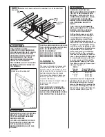
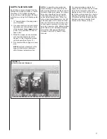
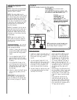
3. If installing on a combustible floor
and not using an air conditioning
plenum,
install the special base for
combustible floors. See Figure 8.
THE DOWNFLOW FURNACE DESIGN
IS CERTIFIED FOR INSTALLATION
ON A NON-COMBUSTIBLE FLOOR.
USE THE SPECIAL BASE SPECIFIED
ON THE FURNACE CLEARANCE
LABEL. FAILURE TO INSTALL THE
SPECIAL BASE MAY RESULT IN
FIRE, PROPERTY DAMAGE, PER-
SONAL INJURY OR DEATH. THIS
SPECIAL BASE IS SHIPPED FROM
THE FACTORY AS AN ACCESSORY.
4. Connect the furnace to the supply
air plenum.
5. Connect the return air ducting to
the return air opening at the top of
the unit. Make the connection air
tight to prevent entraining combus-
tion gases from an adjacent fuel-
burning appliance.
6.
Be sure to have adequate space
for the unit filter.
NOTE:
DO NOT take return air
from bathrooms, kitchens, furnace
rooms, garages, utility or laundry
rooms, or cold areas.
!
WARNING
Return air can come from : (1) out-
side the building, (2) from return air
ducting from several inside rooms, or (3)
a combination of the two. When using
outside air, design and adjust the sys-
tem to maintain a return air temperature
above 55°F
during the heating season.
If return air comes from both inside and
outside the building, design the ducting
system with a diverting damper so that
the volume of return air entering the fur-
nace equals that which would normally
enter through the return air intake of the
furnace. Any duct opening pulling return
air from the outside must not be any
higher nor closer than 10 feet to the fur-
nace exhaust vent.
16
Содержание RGFE
Страница 92: ...92 TABLE 21 FURNACE FAULT CODES EXPANDED W DESCRIPTIONS AND SOLUTIONS CONTINUED ...
Страница 93: ...93 TABLE 21 FURNACE FAULT CODES EXPANDED W DESCRIPTIONS AND SOLUTIONS CONTINUED ...
Страница 94: ...94 TABLE 21 FURNACE FAULT CODES EXPANDED W DESCRIPTIONS AND SOLUTIONS CONTINUED ...
Страница 95: ...95 TABLE 21 FURNACE FAULT CODES EXPANDED W DESCRIPTIONS AND SOLUTIONS CONTINUED ...
Страница 96: ...96 TABLE 21 FURNACE FAULT CODES EXPANDED W DESCRIPTIONS AND SOLUTIONS CONTINUED ...
Страница 97: ...97 TABLE 21 FURNACE FAULT CODES EXPANDED W DESCRIPTIONS AND SOLUTIONS CONTINUED ...
Страница 98: ...98 TABLE 21 FURNACE FAULT CODES EXPANDED W DESCRIPTIONS AND SOLUTIONS CONTINUED ...
Страница 99: ...99 TABLE 21 FURNACE FAULT CODES EXPANDED W DESCRIPTIONS AND SOLUTIONS CONTINUED ...
Страница 101: ...101 TABLE 21 FURNACE FAULT CODES EXPANDED W DESCRIPTIONS AND SOLUTIONS CONTINUED when the inducer is energized at low ...
Страница 102: ...102 TABLE 21 FURNACE FAULT CODES EXPANDED W DESCRIPTIONS AND SOLUTIONS CONTINUED ...
Страница 103: ...103 TABLE 21 FURNACE FAULT CODES EXPANDED W DESCRIPTIONS AND SOLUTIONS CONTINUED ...
Страница 104: ...104 TABLE 21 FURNACE FAULT CODES EXPANDED W DESCRIPTIONS AND SOLUTIONS CONTINUED ...
Страница 105: ...105 TABLE 21 FURNACE FAULT CODES EXPANDED W DESCRIPTIONS AND SOLUTIONS CONTINUED ...
Страница 106: ...106 FIGURE 83 WIRING DIAGRAM STEPPER MODULATING GAS VALVE FUEL CODE HA OR HB FURNACE MODEL IS RGFE RGGE ...
Страница 107: ...107 FIGURE 84 WIRING DIAGRAM SOLENOID CONTROLLED GAS VALVE FUEL CODE HG OR HH FURNACE MODEL RGGE RGFE RGJF ...


