80
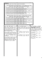
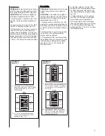
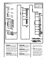
1. COOL AIRFLOW – Displays the
value of the cooling airflow select-
ed. See the section of this manual
titled “DIPSWITCH” under “SW1”
(SW1-1 and SW1-2) for details and
selections.
2. HEAT RISE* – Displays the value
selected for the heat rise (either
nominal or nominal plus ten
degrees F). See the section of
this manual titled “DIPSWITCH”
under “SW1” (SW1-3) for details
and selections.
*ALL TEMPERATURES CAN BE
DISPLAYED ONLY IN FAHREN-
HEIT VALUES
3. HI HEAT ADJ – Displays the value
selected at SW3, positions 4 thru 6.
It is the adjustment of the high heat
rate airflow. See the section of this
manual titled “DIPSWITCH” under
“SW3” (SW3-4 thru SW3-6) for
details and selections.
4. LO HEAT ADJ – Displays the value
selected at SW3, positions 1 thru 3.
It is the adjustment of the low heat
rate airflow. See the section of this
manual titled “DIPSWITCH” under
“SW3” (SW3-1 thru SW3-3) for
details and selections.
5. FAN SPD SELECT – Displays the
fan speed selected. See the sec-
tion of this manual titled “DIP-
SWITCH” under “SW1” (SW3-4) for
details and selections.
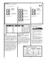
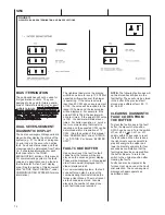
6. AC-HP ADJ
– Adjusts the cooling
or heat-pump airflow slightly to
change or adjust the temperature
rise slightly. See the section of this
manual titled “DIPSWITCH” under
“SW1” (SW1-5 and SW1-6) for
details and selections.
7. ON DEMAND DEHUM – Toggles
the dehumidification feature on or
off. See the section of this manual
titled “DIPSWITCH” under “SW2”
(SW2-1) for details and selections.
8. TST MODE OR STG – Displays
the operation configuration based
on the dipswitch selections. These
selections are explained in detail in
the section of this manual titled
“DIPSWITCH” under “SW2” (SW2-
2 and SW2-3). Further description
follows:
1 STAGING – (SW2-2 = OFF and
SW2-3 = OFF) Represents either
fully modulating operation (when
valid signal is present) or staging
operation when a single stage ther-
mostat is connected.
2 STAGING – (SW2-2 = ON and
SW2-3 = ON) Represents timed
staging operation with a two-stage
thermostat.
40 PRCNT TEST – (SW2-2 = ON
and SW2-3 = OFF) Represents the
mode of operation which will pro-
vide 40% heat rate for any heat call
NOTE: FOR DUAL-FUEL OPERA-
TION, THE SUPPLY AIR SENSOR
MUST BE INSTALLED AND THE
SELECTION FOR THIS SENSOR
SET TO “ON” IN THE “SETUP”
USER MENU UNDER THE SELEC-
TION “SUPPLY AIR SENS” FOR
DUAL-FUEL OPERATION. FAIL-
URE TO INSTALL THE SENSOR
AND TO TURN IT ON IN THE
USER MENUS COULD CAUSE
EXCESSIVE TRIPPING OF THE
PRESSURE LIMIT CONTROLS ON
THE AC SYSTEM.
5. FIXED FIRE RATE – This feature
will temporarily fix the gas heating
fire rate to the selection desired.
The selected rate will be applied to
the present heat call only. If there is
no heat call already present when
the selection is attempted, the sys-
tem will not permit the firing rate to
be fixed at the user menu. The firing
rate and blower will be fixed at the
selected rate for the duration of the
existinig heat call or a
m
aximum of
two hours (whichever comes first).
This feature should only be used for
installation, diagnostic, adjustment
and troubleshooting purposes by an
experienced licensed technician.
Selectable firing rates are 40%,
50%, 60%, 70%, 75%, 80%, 85%,
90% and 100%.
6. RESET ALL DFLTS
– This selec-
tion restores all items in the
“SETUP” menu to the factory default
selections. If “yES” is selected, all
settings in this menu will be lost.
NOTE:
When faults are cleared in
the furnace “SETUP” user menu,
the continuous fan CFM will also be
restored to the factory default set-
ting. (See Continuous Fan
Operation in Communicating Mode.)
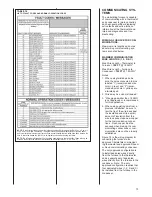
BELOW USER MENU IS USED FOR
NON-COMMUNICATING SYSTEMS
ONLY
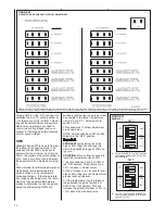
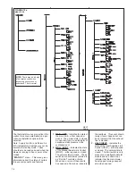
“DIPSWITCH”
menu – This menu per-
mits viewing of the dipswitch selections.
It is a way to read the dipswitch selec-
tions without the need of translating the
settings manually.
Note: The “DIPSWITCH” menus will not
be displayed at the thermostat. They
are invisible to the thermostat and can
not be displayed. These menus can
only be viewed with the field service
tool. The reason is that dipswitch selec-
tions do not generally affect operation of
the furnace when using the communi-
cating mode of operation.
NOTE:
The integrated furnace control
does not recognize switch setting
changes while energized. To change
settings, remove power to the board by
turning off the disconnect or switch to
the furnace control or removing power
at the breaker, make changes, then
return power.
– regardless of the rate transmit-
ted by the thermostat. This
mode ends automatically after
the first 60 minutes of operation
after power-up.
100 PRCNT TEST – (SW2-2 =
OFF and SW2-3 = ON)
Represents the mode of opera-
tion which will provide 100%
heat rate for any heat call –
regardless of the rate transmit-
ted by the thermostat. This
mode ends automatically after
the first 60 minutes of operation
after power-up.
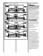
9. AC HP STG MULT – This allows
for adjustment to the airflow for
low-stage of cooling and heat-
pump operation. See the sec-
tion of this manual titled “DIP-
SWITCH” under “SW2” (SW2-4)
for details and selections.
DUAL-FUEL OPERATION IN COM-
MUNICATING MODE
Systems configured for dual-fuel
operation will include a communicat-
ing condenser with a reversing
valve. Dual-fuel systems will display
“
HP” for Heat-Pump heat operation
at the furnace control’s (I.F.C.) dual
seven-segment displays. During
defrost mode, “
dF” will be displayed.
All other codes apply.
The balance point can be adjusted
at the thermostat for optimal opera-
tion. The balance point is the point
below which gas heat will be used
and above which heat-pump heat
will be used.
For dual-fuel systems, to protect
equipment, the supply air sensor
must be installed. When the supply
air sensor is properly installed and
the system is in
defrost
mode, the
gas heat will only operate when the
outlet air is below 110°F. When the
outlet air exceeds 110°F, the gas
valve is turned off and the Air
Circulating Blower (ACB) continues
to run. When the supply air tempera-
ture reaches 95°F, the gas heat will
again be turned on. This cycle will
continue until the call for defrost has
ended.
NOTE:
FOR DUAL-FUEL OPERA-
TION, THE SUPPLY AIR SENSOR
MUST BE INSTALLED AND THE
SELECTION FOR THIS SENSOR
SET TO “ON” IN THE “SETUP”
USER MENU UNDER THE SELEC-
TION “SUPPLY AIR SENS” FOR
DUAL-FUEL OPERATION. FAIL-
URE TO INSTALL THE SENSOR
AND TO TURN IT ON IN THE
USER MENUS COULD CAUSE
EXCESSIVE TRIPPING OF THE
PRESSURE LIMIT CONTROLS ON
THE AC SYSTEM.
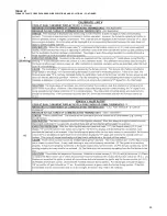
Содержание RGFE
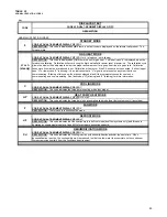
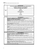
Страница 92: ...92 TABLE 21 FURNACE FAULT CODES EXPANDED W DESCRIPTIONS AND SOLUTIONS CONTINUED ...
Страница 93: ...93 TABLE 21 FURNACE FAULT CODES EXPANDED W DESCRIPTIONS AND SOLUTIONS CONTINUED ...
Страница 94: ...94 TABLE 21 FURNACE FAULT CODES EXPANDED W DESCRIPTIONS AND SOLUTIONS CONTINUED ...
Страница 95: ...95 TABLE 21 FURNACE FAULT CODES EXPANDED W DESCRIPTIONS AND SOLUTIONS CONTINUED ...
Страница 96: ...96 TABLE 21 FURNACE FAULT CODES EXPANDED W DESCRIPTIONS AND SOLUTIONS CONTINUED ...
Страница 97: ...97 TABLE 21 FURNACE FAULT CODES EXPANDED W DESCRIPTIONS AND SOLUTIONS CONTINUED ...
Страница 98: ...98 TABLE 21 FURNACE FAULT CODES EXPANDED W DESCRIPTIONS AND SOLUTIONS CONTINUED ...
Страница 99: ...99 TABLE 21 FURNACE FAULT CODES EXPANDED W DESCRIPTIONS AND SOLUTIONS CONTINUED ...
Страница 101: ...101 TABLE 21 FURNACE FAULT CODES EXPANDED W DESCRIPTIONS AND SOLUTIONS CONTINUED when the inducer is energized at low ...
Страница 102: ...102 TABLE 21 FURNACE FAULT CODES EXPANDED W DESCRIPTIONS AND SOLUTIONS CONTINUED ...
Страница 103: ...103 TABLE 21 FURNACE FAULT CODES EXPANDED W DESCRIPTIONS AND SOLUTIONS CONTINUED ...
Страница 104: ...104 TABLE 21 FURNACE FAULT CODES EXPANDED W DESCRIPTIONS AND SOLUTIONS CONTINUED ...
Страница 105: ...105 TABLE 21 FURNACE FAULT CODES EXPANDED W DESCRIPTIONS AND SOLUTIONS CONTINUED ...
Страница 106: ...106 FIGURE 83 WIRING DIAGRAM STEPPER MODULATING GAS VALVE FUEL CODE HA OR HB FURNACE MODEL IS RGFE RGGE ...
Страница 107: ...107 FIGURE 84 WIRING DIAGRAM SOLENOID CONTROLLED GAS VALVE FUEL CODE HG OR HH FURNACE MODEL RGGE RGFE RGJF ...


