38
CONDENSATE DRAIN
FOR HORIZONTAL
(RGJF) INSTALLATION
DEDICATED HORIZONTAL (RGJF)
MODELS ARE SHIPPED WITHOUT
A DRAIN TRAP ATTACHED. IT
MUST BE ATTACHED (AS
DESCRIBED BELOW) IN THE
FIELD. FAILURE TO INSTALL THE
DRAIN TRAP AS DESCRIBED CAN
CAUSE THE FURNACE TO SHUT
DOWN UNEXPECTEDLY.
NOTE: The following steps should
take place with the furnace in the
horizontal position.
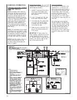
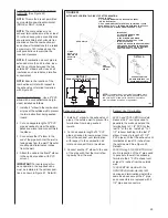
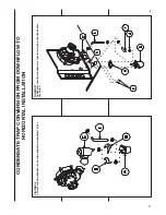
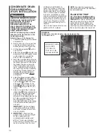
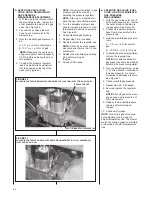
Refer to Figure 37 for Steps 1-8.
1. Locate the parts bag in the burner
compartment.
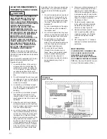
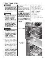
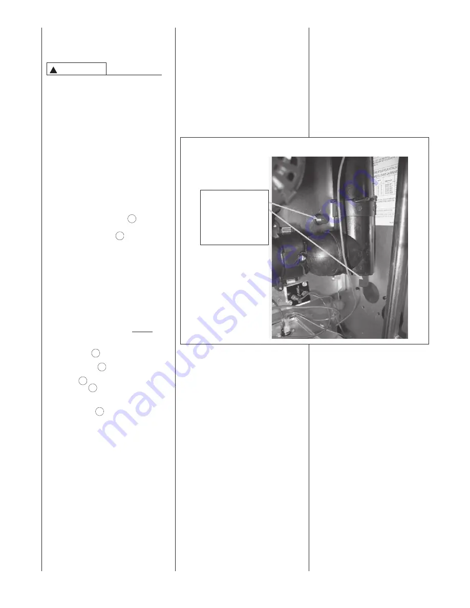
2. Remove the red vinyl covers that
cover the vent drain and heat
exchanger drain (see Figure 38).
3. Fill the trap assembly
with a
cup of water.
4. Attach the gasket
onto the trap
assembly so that the gasket holes
on the gasket line up with the
holes on the trap assembly.
5. Insert the trap assembly with gas-
ket up through the existing hole in
the jacket and secure from inside
the jacket. Use two screws pro-
vided. Screw down into the two
“ears” molded into either side of
the trap. Snug the trap assembly
against the furnace jacket com-
pressing the gasket slightly to
eliminate any air leaks. Do not
overtighten!
6. Attach the black molded rubber
90° elbow
to the straight spout
on the trap top using a black
nylon clamp . Attach the other
end of the rubber elbow to the
spout
located on the exhaust
transition
using a black nylon
clamp.
7. Attach one end of the horizontal
ribbed tube
to the collector box.
Clamp the hose tight with black
nylon clamp. Then attach the
other end of the ribbed tube to the
45° elbow molded into the top of
the trap assembly. Clamp the
hose tight with black nylon clamp.
The horizontal ribbed tube is 6.7”
in length.
IMPORTANT: Tighten all clamp
connections with a pair of pliers
and check for leaks after conver-
sion is complete.
8.
IMPORTANT: There are two
options when choosing a height
for the condensate riser:
CONDENSATE OVERFLOW:
With a 1
3
⁄
4
inch riser installed
above the tee, a blocked drain will
result in overflow from the riser.
FURNACE SHUTDOWN: To
cause the furnace to shut down
when a blocked drain is present,
install a riser which is a minimum
of 5
1
⁄
2
”. If the furnace is installed
in an attic, crawlspace or other
area where freezing temperatures
may occur, the furnace drain can
freeze while shut off for long peri-
ods of time. Provisions must be
made to prevent freezing of con-
densate.
Use a solvent cement that is com-
patible with PVC material.
NOTE:
See location requirements
and combustion section for additional
recommendations.
FILLING THE TRAP
FILL THE TRAP ASSEMBLY WITH
WATER BEFORE OPERATING THE
FURNACE.
Do this by removing the
drain hose from the trap or from the
connection to the secondary coil.
Pour about a cup of water into the
vent trap. Any excess water flows into
the house drain when the trap is full.
FIGURE 38
REMOVE VINYL CAPS BEFORE INSTALLING THE DRAIN SYSTEM.
(-GJF MODELS ONLY)
!
WARNING
REMOVE THESE
RED VINYL
COVERS TO
INSTALL THE
DRAIN SYSTEM
G
H
I
J
K
E
L
Содержание RGFE
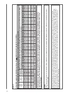
Страница 92: ...92 TABLE 21 FURNACE FAULT CODES EXPANDED W DESCRIPTIONS AND SOLUTIONS CONTINUED ...
Страница 93: ...93 TABLE 21 FURNACE FAULT CODES EXPANDED W DESCRIPTIONS AND SOLUTIONS CONTINUED ...
Страница 94: ...94 TABLE 21 FURNACE FAULT CODES EXPANDED W DESCRIPTIONS AND SOLUTIONS CONTINUED ...
Страница 95: ...95 TABLE 21 FURNACE FAULT CODES EXPANDED W DESCRIPTIONS AND SOLUTIONS CONTINUED ...
Страница 96: ...96 TABLE 21 FURNACE FAULT CODES EXPANDED W DESCRIPTIONS AND SOLUTIONS CONTINUED ...
Страница 97: ...97 TABLE 21 FURNACE FAULT CODES EXPANDED W DESCRIPTIONS AND SOLUTIONS CONTINUED ...
Страница 98: ...98 TABLE 21 FURNACE FAULT CODES EXPANDED W DESCRIPTIONS AND SOLUTIONS CONTINUED ...
Страница 99: ...99 TABLE 21 FURNACE FAULT CODES EXPANDED W DESCRIPTIONS AND SOLUTIONS CONTINUED ...
Страница 101: ...101 TABLE 21 FURNACE FAULT CODES EXPANDED W DESCRIPTIONS AND SOLUTIONS CONTINUED when the inducer is energized at low ...
Страница 102: ...102 TABLE 21 FURNACE FAULT CODES EXPANDED W DESCRIPTIONS AND SOLUTIONS CONTINUED ...
Страница 103: ...103 TABLE 21 FURNACE FAULT CODES EXPANDED W DESCRIPTIONS AND SOLUTIONS CONTINUED ...
Страница 104: ...104 TABLE 21 FURNACE FAULT CODES EXPANDED W DESCRIPTIONS AND SOLUTIONS CONTINUED ...
Страница 105: ...105 TABLE 21 FURNACE FAULT CODES EXPANDED W DESCRIPTIONS AND SOLUTIONS CONTINUED ...
Страница 106: ...106 FIGURE 83 WIRING DIAGRAM STEPPER MODULATING GAS VALVE FUEL CODE HA OR HB FURNACE MODEL IS RGFE RGGE ...
Страница 107: ...107 FIGURE 84 WIRING DIAGRAM SOLENOID CONTROLLED GAS VALVE FUEL CODE HG OR HH FURNACE MODEL RGGE RGFE RGJF ...

