71
EXAMPLE 3
PROBLEM:
Temperature rise is too low
at 40% firing rate and is too high at
100%.
SOLUTION:
Less airflow is needed to
increase temperature rise at 40% firing
rate and more is needed to decrease
temperature rise at 100%.
1) Set dip switch 4 of SW3 to the “ON”
position to override standard airflow at
40% firing rate. Leave switches 5 and 6
in “OFF” position to decrease airflow by
7.5%.
2) Allow furnace to run for several min-
utes at 40% rate until temperature
probes reach equilibrium.
3) If temperature rise is still lower than
the published range, set switch 6 to the
“ON” position to decrease the airflow
rate from -7.5% to -15% below the
standard value.
EXAMPLE 2
PROBLEM:
Temperature rise is too low
at 100% firing rate although it is within
the published range at 40% firing rate.
SOLUTION:
Less airflow is needed to
increase temperature rise at 100%.
1) Set dip switch 1 of SW3 to the “ON”
position, which overrides standard air-
flow.
2) Leave switches 2 and 3 in the “OFF”
position to decrease airflow by 7.5%.
3) Allow furnace to run for several min-
utes at 100% rate until temperature
probes reach equilibrium. 4) If the tem-
perature rise is still below the published
range, set switch 3 to the “ON” position.
This will decrease the airflow rate from
7.5% to -15% below the standard value.
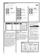
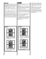
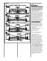
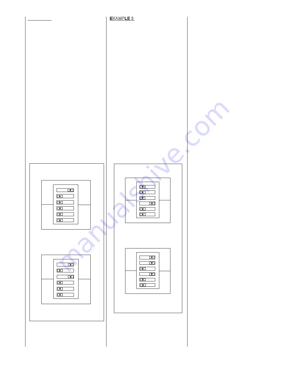
FIGURE 71
EXAMPLE 2
123456
ON
OFF
40%
100%
SW3
STD
--
7.5%
STD
--
7.5%
ADJ
+
15%
ADJ
+
15%
A. Set switch #1 to “ON” position and
leave #2 and #3 in the “OFF” position
to decrease airflow by 7.5% at the
100% fire rate.
123456
ON
OFF
40%
100%
SW3
STD
--
7.5%
STD
--
7.5%
ADJ
+
15%
ADJ
+
15%
B. If -7.5% is not enough, decrease
airflow by setting switch 3 to “ON”
position to give -15%.
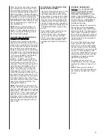
FIGURE 72
EXAMPLE 3
123456
ON
OFF
40%
100%
SW3
STD
--
7.5%
STD
--
7.5%
ADJ
+
15%
ADJ
+
15%
A. Set switch #4 to “ON” and leave #5 and
#6 set to “OFF” to decrease airflow by
7.5% at the 40% fire rate. If necessary,
set switch #6 to “ON” to decrease air-
flow by 15%.
123456
ON
OFF
40%
100%
SW3
STD
--
7.5%
STD
--
7.5%
ADJ
+
15%
ADJ
+
15%
B. Set switches #1 and #2 to “ON” and
leave #3 set to “OFF” to increase air-
flow by 7.5% at the 100% fire rate. If
necessary, set switch #3 to “ON” to
increase airflow by 15%.
4) Set dip switches 1 to the “ON”
position to override standard airflow
at 100% firing rate. Set switch 2 to
the “ON” position to increase airflow
by 7.5%.
5) Allow furnace to run for several
minutes at 100% rate until temper-
ature probes reach equilibrium.
6) If temperature rise is still higher
than the published range, set switch
3 to “ON” position to increase the
airflow rate from 7.5% to 15% above
the standard value.
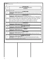
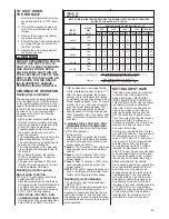
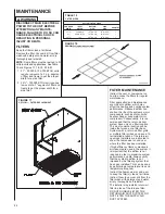
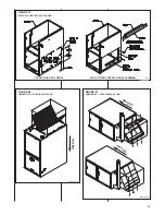
Содержание RGFE
Страница 92: ...92 TABLE 21 FURNACE FAULT CODES EXPANDED W DESCRIPTIONS AND SOLUTIONS CONTINUED ...
Страница 93: ...93 TABLE 21 FURNACE FAULT CODES EXPANDED W DESCRIPTIONS AND SOLUTIONS CONTINUED ...
Страница 94: ...94 TABLE 21 FURNACE FAULT CODES EXPANDED W DESCRIPTIONS AND SOLUTIONS CONTINUED ...
Страница 95: ...95 TABLE 21 FURNACE FAULT CODES EXPANDED W DESCRIPTIONS AND SOLUTIONS CONTINUED ...
Страница 96: ...96 TABLE 21 FURNACE FAULT CODES EXPANDED W DESCRIPTIONS AND SOLUTIONS CONTINUED ...
Страница 97: ...97 TABLE 21 FURNACE FAULT CODES EXPANDED W DESCRIPTIONS AND SOLUTIONS CONTINUED ...
Страница 98: ...98 TABLE 21 FURNACE FAULT CODES EXPANDED W DESCRIPTIONS AND SOLUTIONS CONTINUED ...
Страница 99: ...99 TABLE 21 FURNACE FAULT CODES EXPANDED W DESCRIPTIONS AND SOLUTIONS CONTINUED ...
Страница 101: ...101 TABLE 21 FURNACE FAULT CODES EXPANDED W DESCRIPTIONS AND SOLUTIONS CONTINUED when the inducer is energized at low ...
Страница 102: ...102 TABLE 21 FURNACE FAULT CODES EXPANDED W DESCRIPTIONS AND SOLUTIONS CONTINUED ...
Страница 103: ...103 TABLE 21 FURNACE FAULT CODES EXPANDED W DESCRIPTIONS AND SOLUTIONS CONTINUED ...
Страница 104: ...104 TABLE 21 FURNACE FAULT CODES EXPANDED W DESCRIPTIONS AND SOLUTIONS CONTINUED ...
Страница 105: ...105 TABLE 21 FURNACE FAULT CODES EXPANDED W DESCRIPTIONS AND SOLUTIONS CONTINUED ...
Страница 106: ...106 FIGURE 83 WIRING DIAGRAM STEPPER MODULATING GAS VALVE FUEL CODE HA OR HB FURNACE MODEL IS RGFE RGGE ...
Страница 107: ...107 FIGURE 84 WIRING DIAGRAM SOLENOID CONTROLLED GAS VALVE FUEL CODE HG OR HH FURNACE MODEL RGGE RGFE RGJF ...

