➤
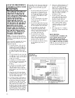
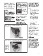
SERVO GAS VALVE (FUEL
➤
CODE: HA OR HB) MANIFOLD
➤
GAS PRESSURE
➤
MEASUREMENT/ADJUSTMENT.
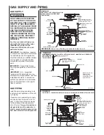
1. With the gas to the unit shut off at
the manual gas valve, remove the
outlet pressure tap plug in the gas
valve. See Figure 48.
2. Connect the positive pressure
hose from a manometer to the
pressure tap.
3. Note the manifold gas pressure to
be:
A. 3.5" w.c. (±.3) for natural gas .
B. 10.0" w.c. ( ±.5) for LP gas.
NOTE:
Make sure the unit is oper-
ating at maximum heating capacity
(100%) before adjusting the mani-
fold pressure.
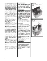
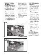
4. To adjust the pressure regulator,
insert a small slotted screwdriver
into the opening at the top of the
valve (see Figure 49).
NOTE:
Only small variations in gas
pressure should be made by
adjusting the pressure regulator.
NOTE:
Allow up to 5 seconds for
each change in manifold pressure.
5. Turn the adjustm
ent screw clock-
wise to increase pressure, or coun-
terclockwise to decrease pressure.
See Figure 49.
6. Check manifold gas pressure.
7. Repeat step 5 & 6 if needed.
8. Securely replace the regulator cap.
NOTE:
Shut off gas at the manual
gas valve and remove the U-Tube
manometer.
9. Replace the manifold pressure tap
plug before turning on
the gas.
10. Check unit for leaks.
➤
SOLENOID GAS VALVE (FUEL
➤
CODE: HG OR HH) MANIFOLD
➤
GAS PRESSURE
➤
MEASUREMENT.
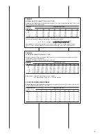
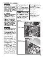
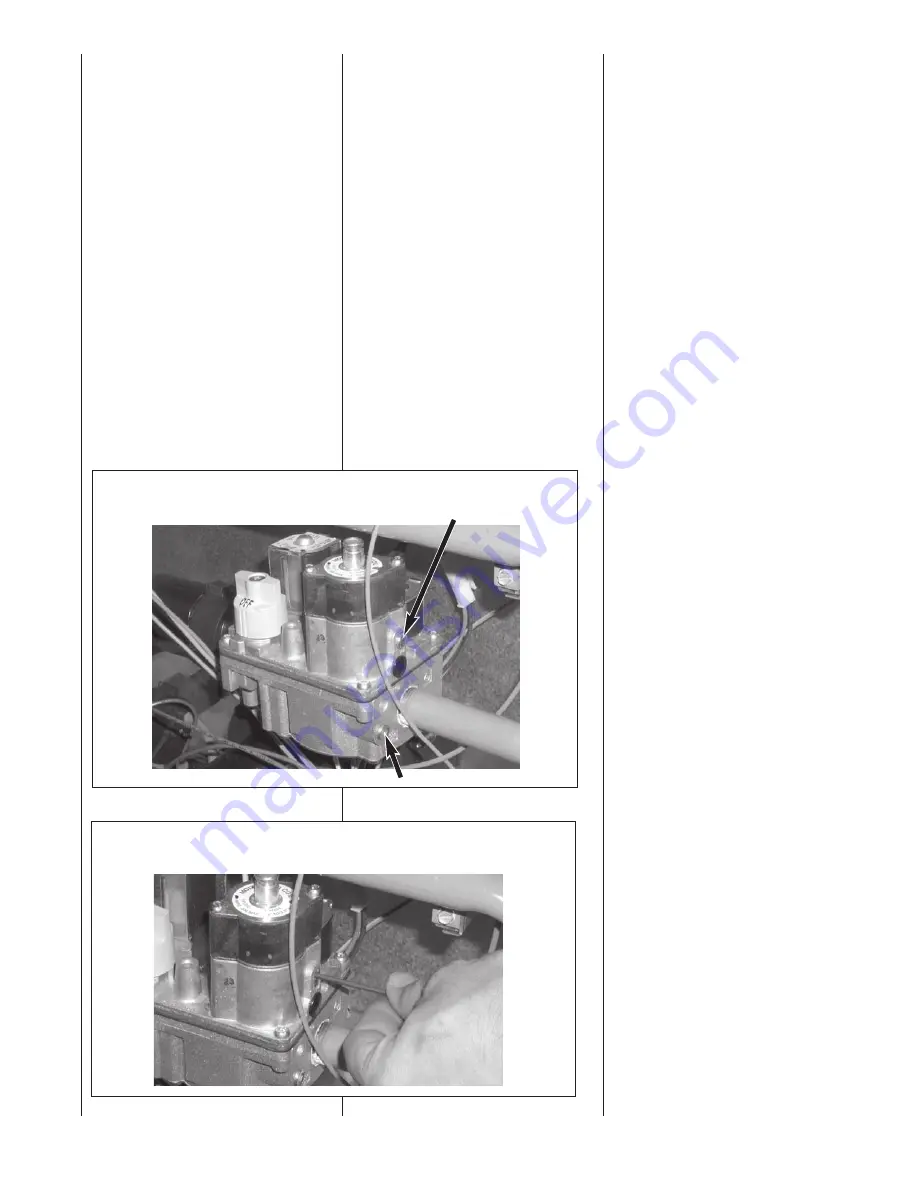
1. With the gas to the unit shut off
at the manual gas valve, remove
the outlet pressure tap plug in
the gas valve. See Figure 50.
2. Connect the positive pressure
hose from a manometer to the
pressure tap.
3. Note the manifold gas pressure
to be:
A. 3.5" w.c. (±.3) for natural
gas .
B. 10.0" w.c. ( ±.5) for LP gas.
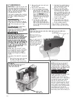
4. To adjust the pressure regulator,
remove the regulator cap.
NOTE:
Only small variations in
gas pressure should be made by
adjusting the pressure regulator.
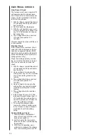
5. Turn the adjustment screw, using
a
3
⁄
32
" allen wrench, clockwise to
increase pressure, or counter-
clockwise to decrease pressure.
See Figure 51.
6. Check manifold gas pressure.
7. Repeat step 5 & 6 if needed.
8. Securely replace the regulator
cap.
NOTE:
Shut off gas at the manu-
al gas valve and remove the U-
Tube manometer.
9. Replace the manifold pressure
tap plug before turning on
the gas.
10. Check unit for leaks.
NOTE:
Do not use gas valve pres-
sure adjustment as a means to
adjust temperature rise. The blower
motor will change speed to maintain
a reasonably constant temperature
rise.
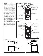
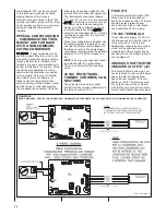
FIGURE 50
SOLENOID CONTROLLED MANIFOLD PRESSURE TAP LOCATION (FUEL CODE HA OR HB)
OUTLET MANIFOLD PRESSURE TAP
FIGURE 51
SOLENOID CONTROLLED GAS VALVE PRESSURE ADJUSTMENT (3/32" ALLEN WRENCH)
(FUEL CODE HH OR HG)
REGULATOR CAP
44
Содержание RGFE
Страница 92: ...92 TABLE 21 FURNACE FAULT CODES EXPANDED W DESCRIPTIONS AND SOLUTIONS CONTINUED ...
Страница 93: ...93 TABLE 21 FURNACE FAULT CODES EXPANDED W DESCRIPTIONS AND SOLUTIONS CONTINUED ...
Страница 94: ...94 TABLE 21 FURNACE FAULT CODES EXPANDED W DESCRIPTIONS AND SOLUTIONS CONTINUED ...
Страница 95: ...95 TABLE 21 FURNACE FAULT CODES EXPANDED W DESCRIPTIONS AND SOLUTIONS CONTINUED ...
Страница 96: ...96 TABLE 21 FURNACE FAULT CODES EXPANDED W DESCRIPTIONS AND SOLUTIONS CONTINUED ...
Страница 97: ...97 TABLE 21 FURNACE FAULT CODES EXPANDED W DESCRIPTIONS AND SOLUTIONS CONTINUED ...
Страница 98: ...98 TABLE 21 FURNACE FAULT CODES EXPANDED W DESCRIPTIONS AND SOLUTIONS CONTINUED ...
Страница 99: ...99 TABLE 21 FURNACE FAULT CODES EXPANDED W DESCRIPTIONS AND SOLUTIONS CONTINUED ...
Страница 101: ...101 TABLE 21 FURNACE FAULT CODES EXPANDED W DESCRIPTIONS AND SOLUTIONS CONTINUED when the inducer is energized at low ...
Страница 102: ...102 TABLE 21 FURNACE FAULT CODES EXPANDED W DESCRIPTIONS AND SOLUTIONS CONTINUED ...
Страница 103: ...103 TABLE 21 FURNACE FAULT CODES EXPANDED W DESCRIPTIONS AND SOLUTIONS CONTINUED ...
Страница 104: ...104 TABLE 21 FURNACE FAULT CODES EXPANDED W DESCRIPTIONS AND SOLUTIONS CONTINUED ...
Страница 105: ...105 TABLE 21 FURNACE FAULT CODES EXPANDED W DESCRIPTIONS AND SOLUTIONS CONTINUED ...
Страница 106: ...106 FIGURE 83 WIRING DIAGRAM STEPPER MODULATING GAS VALVE FUEL CODE HA OR HB FURNACE MODEL IS RGFE RGGE ...
Страница 107: ...107 FIGURE 84 WIRING DIAGRAM SOLENOID CONTROLLED GAS VALVE FUEL CODE HG OR HH FURNACE MODEL RGGE RGFE RGJF ...

