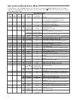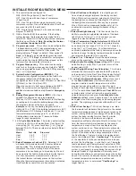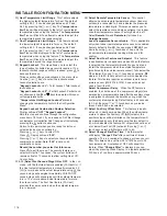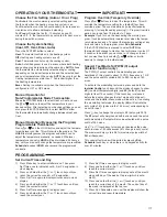
116
53
20)
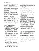
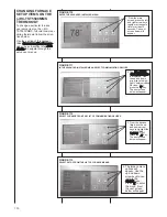
Heat Temperature Limit Range
This f eature adjusts
the highest setpoint temperature for heat. The default
setting is 99 F. It can be changed between 62 F and
98 F b y pressing the
or
key. The "
temperature
limit
" icon will be displayed to the left of your setpoint
temperature when using this feature. The "
temperature
limit
" icon will flash if an attempt is made to adjust the
temperature beyond the range selected.
21)
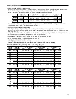
Cool Temperature Limit Range
T his feature adjusts
the lowest setpoint temperature for cool. The default
setting is 45 F. It can be changed between 46 F and
82 F b y pressing the
or
key. The "
temperature
limit
" icon will be displayed to the left of your setpoint
temperature when using this feature. The "
temperature
limit
" icon will flash if an attempt is made to adjust the
temperature beyond the range selected.
22)
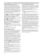
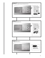
Keypad Lockout
This step allows y ou to select the
type of lockout or limited range security required. If no
lockout or limited range security is required, press
to
advance the menu.
Three security settings are available in this menu item.
Use the
or
keys to select the lockout desired.
Lockout selections are:
"
Keypad Lockout
and
L
" = Total Lockout. Total Lockout
locks all keys.
"
Keypad Lockout
and
P
" = Partial Lockout. Partial Lock-
out allows only the
or
keys to operate within your
set temperature limits.
"
Temperature Limit
/
Keypad Lockout
" prevents
changing the temperature limits in the Configuration
Menu.
Keypad Lockout Combination Number Selection
Display will read "
OFF
" "
Keypad Lockout
".
Skip this step and continue through the configuration
menu items 19 thru 22 if you require an Air Filter Change
out indicator or Humidifier Pad Change out indicator by
pressing the
button to advance.
Return to this point when you are ready to start your
selected lock-out and continue by:
Pressing
or
keys to select ON.
Press
. Display will read "
000
".
Pressing
or
keys to select your keypad lockout
combination number. Note: "
000
" is not a valid
combination choice.
Record the number you select for future use.
Press
to exit the menu. The security feature you
select will start in 10 seconds. The system button will
remain active for 10 seconds to allow setting Heat, Off,
Cool or Auto.
23 & 24)
Select Fast Second Stage ON or OFF
In the r un
mode, with the fast Heat feature enabled (FA Heat On), if
the Heat setpoint temperature is manually raised by 3 F
(2 C) or more a bove the actual temperature using
the
second stage will energize immediately. With FA OFF,
second stage will not energize until the setpoint tempera-
ture is 1 F or more a bove actual temperature for more
than ten minutes. The Fast Cool feature (FA Cool)
provides the same controls when the setpoint tempera-
ture is lowered.
INSTALLER/CONFIGURATION MENU
25)
Select Remote Temperature Sensor
This control
allows one wired remote temperature sensor (indoor or
outdoor) be connected to it and indicates the measured
temperature in clock digits. This menu enables you to
select the remote sensor and also configure it as indoor
or outdoor temperature sensor. Factory default is off.
Select
Remote On
and
Remote in
(for indoor) or
Outdoor Remote
.
Local Temperature Sensor disable
This is applica ble
only when indoor remote temperature sensor is enabled.
Factory default is
On LS
. You can make it
Off LS
if you
desire by using
or
touch keys.Then, only the
indoor remote temperature reading will be used for
control.
26)
Select Dual Fuel Feature and Setpoint
This f eature
is applicable only in heat pump modes. When the feature
is selected, the thermostat will switch to gas heat and
inhibit the compressor when the outside temperature
(monitored by the outside remote sensor), falls below the
DF setpoint. By using
or
touch keys, select
x
,
DF
where x=5 to 50; factory default is 5 which disables the
feature. This feature requires an outdoor remote temp-
erature sensor (WR# F145-1378), however does not
need a fossil fuel kit.
Select Compressor Delay
When the DF feature is
enabled, the shut down of the compressor stage(s) are
delayed by a programmable time after the auxiliary stage
is energized to minimize the duration during which the
system may blow cooler air. Default delay is 60 seconds
(60, Cd). By using
or
touch keys any value be-
tween 0 and 99 can be selected.
27)
Select Auxiliary Offset Point
T his feature is applic-
able only in heat pump modes. When the outdoor temp-
erature is above the Auxiliary Off (
AO
) setpoint, the
auxiliary stages will be inhibited so the temperature will
be maintained by only the heat pump. Factory default is
80, which disables the feature. AO setpoint cannot be set
at or below Dual Fuel (DF) setpoint. By using
or
touch keys, select
x
,
AO
where x=35 to 80.
28)
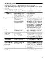
Select Change Filter Run Time
The ther mostat
will display "
Change Filter
" after a set time of blower
operation. This is a reminder to change or clean your air
filter. This time can be set from 25 to 1975 hours in 25
hour increments. A selection of OFF will cancel this
feature. When "
Change Filter
" is displayed, you can
clear it by pressing Clean Display. In a typical application,
200 hours of run time is approximately 30 days.
Содержание RGFE
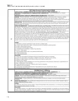
Страница 92: ...92 TABLE 21 FURNACE FAULT CODES EXPANDED W DESCRIPTIONS AND SOLUTIONS CONTINUED ...
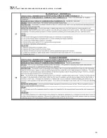
Страница 93: ...93 TABLE 21 FURNACE FAULT CODES EXPANDED W DESCRIPTIONS AND SOLUTIONS CONTINUED ...
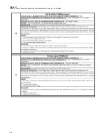
Страница 94: ...94 TABLE 21 FURNACE FAULT CODES EXPANDED W DESCRIPTIONS AND SOLUTIONS CONTINUED ...
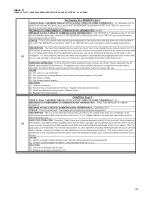
Страница 95: ...95 TABLE 21 FURNACE FAULT CODES EXPANDED W DESCRIPTIONS AND SOLUTIONS CONTINUED ...
Страница 96: ...96 TABLE 21 FURNACE FAULT CODES EXPANDED W DESCRIPTIONS AND SOLUTIONS CONTINUED ...
Страница 97: ...97 TABLE 21 FURNACE FAULT CODES EXPANDED W DESCRIPTIONS AND SOLUTIONS CONTINUED ...
Страница 98: ...98 TABLE 21 FURNACE FAULT CODES EXPANDED W DESCRIPTIONS AND SOLUTIONS CONTINUED ...
Страница 99: ...99 TABLE 21 FURNACE FAULT CODES EXPANDED W DESCRIPTIONS AND SOLUTIONS CONTINUED ...
Страница 101: ...101 TABLE 21 FURNACE FAULT CODES EXPANDED W DESCRIPTIONS AND SOLUTIONS CONTINUED when the inducer is energized at low ...
Страница 102: ...102 TABLE 21 FURNACE FAULT CODES EXPANDED W DESCRIPTIONS AND SOLUTIONS CONTINUED ...
Страница 103: ...103 TABLE 21 FURNACE FAULT CODES EXPANDED W DESCRIPTIONS AND SOLUTIONS CONTINUED ...
Страница 104: ...104 TABLE 21 FURNACE FAULT CODES EXPANDED W DESCRIPTIONS AND SOLUTIONS CONTINUED ...
Страница 105: ...105 TABLE 21 FURNACE FAULT CODES EXPANDED W DESCRIPTIONS AND SOLUTIONS CONTINUED ...
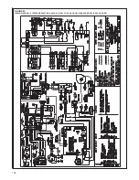
Страница 106: ...106 FIGURE 83 WIRING DIAGRAM STEPPER MODULATING GAS VALVE FUEL CODE HA OR HB FURNACE MODEL IS RGFE RGGE ...
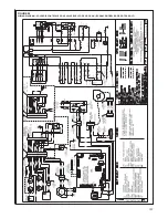
Страница 107: ...107 FIGURE 84 WIRING DIAGRAM SOLENOID CONTROLLED GAS VALVE FUEL CODE HG OR HH FURNACE MODEL RGGE RGFE RGJF ...

