507335-01
Page 1 of 44
Issue 1624
This is a safety alert symbol and should never be ignored. When you see this symbol on labels or in
manuals, be alert to the potential for personal injury or death.
Manufactured By
Allied Air Enterprises, Inc.
A Lennox International, Inc. Company
215 Metropolitan Drive
West Columbia, SC 29170
*P507335-01*
(P) 507335-01
This manual must be left with the homeowner for future reference.
INSTALLATION INSTRUCTIONS
A80UH2V & 80G2UH-V
Warm Air Gas Furnace
Upflow / Horizontal Left and Right Air Discharge
Improper installation, adjustment, alteration, service
or maintenance can cause property damage, personal
injury or loss of life. Installation and service must
be performed by a licensed professional installer (or
equivalent), service agency or the gas supplier.
WARNING
As with any mechanical equipment, personal injury can
result from contact with sharp sheet metal edges. Be
careful when you handle this equipment.
CAUTION
Table of Contents
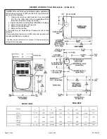
Unit Dimensions ......................................................................2
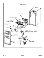
Parts Arrangement...................................................................3
A80UH2V & 80G2UH-V Gas Furnace
.....................................4
Shipping and Packing List .......................................................4
Safety Information ...................................................................4
Use of Furnace as a Construction Heater
...............................5
General ....................................................................................6
Combustion, Dilution & Ventilation Air
.....................................6
Setting Equipment ...................................................................9
Filters .....................................................................................12
Duct System ..........................................................................12
...................................................................................13
Gas Piping .............................................................................23
Electrical ................................................................................25
Start-Up .................................................................................30
Gas Pressure Adjustment ......................................................31
..........................................................................32
Sequence of Operation .........................................................33
Maintenance ..........................................................................36
Control Diagnostics ...............................................................39
Planned Service ....................................................................40
Repair Parts List ....................................................................40
Wiring Diagram ......................................................................41
Содержание 80G2UH-V
Страница 29: ...507335 01 Page 29 of 44 Issue 1624 ADJUSTING AIRFLOW Table 11 ...
Страница 37: ...507335 01 Page 37 of 44 Issue 1624 Burner Combustion Air Inducer Assembly and Heat Exchanger Removal Figure 38 ...
Страница 41: ...507335 01 Page 41 of 44 Issue 1624 Wiring Diagram Figure 41 ...
Страница 42: ...507335 01 Page 42 of 44 Issue 1624 Typical Field Wiring Diagram Figure 42 ...
Страница 43: ...507335 01 Page 43 of 44 Issue 1624 Start Up Performance Check List UNIT SET UP ...
Страница 44: ...507335 01 Page 44 of 44 Issue 1624 UNIT OPERATION ...


