


507335-01
Page 26 of 44
Issue 1624
4. Before connecting the thermostat, check to make sure
the wires will be long enough for servicing at a later
date. Make sure that thermostat wire is long enough
to facilitate future removal of blower for service.
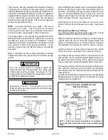
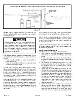
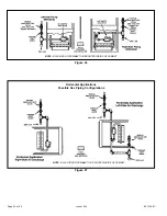
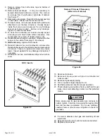
5. Complete the wiring connections to the equipment. Use
the provided unit wiring diagram and the field wiring
diagram shown in Figure 42. Use 18 gauge wire or
larger that is suitable for Class II rating for thermostat
connections.
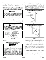
6. Electrically ground the unit according to local codes or,
in the absence of local codes, according to the current
National Electric Code (ANSI/NFPA No. 70). A green
ground wire is provided in the field make-up box.
NOTE:
This furnace contains electronic components that
are polarity sensitive. Make sure that the furnace is wired
correctly and is properly grounded.
7. One line voltage “EAC” 1/4” spade terminal is provided
on the furnace integrated control. Any electronic air
cleaner or other accessory rated up to one amp can
be connected to this terminal with the neutral leg of the
circuit being connected to one of the provided neutral
terminals. See Figure 42 for control configuration.
This terminal is energized when the indoor blower is
operating.
8. One line voltage “HUM” 1/4” spade terminal is provided
on the furnace integrated control. Any humidifier rated
up to one amp can be connected to this terminal with
the neutral leg of the circuit being connected to one of
the provided neutral terminals. See Figure 42 for control
configuration. This terminal is energized in the heating
mode whenever the combustion air inducer is operating.
9. Install the room thermostat according to the instructions
provided with the thermostat. If the furnace is being
matched with a heat pump, refer to the instruction
packaged with the dual fuel thermostat.
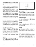
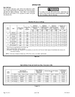
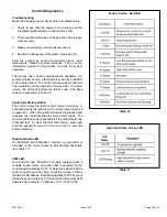
Indoor Blower Speeds
1. When the thermostat is set to “FAN ON,” the indoor
blower will run continuously at approximately 50% of the
second stage cooling speed when there is no cooling
or heating demand.
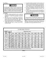
2. When this unit is running in the heating mode, the indoor
blower will run on the heating speed designated by
the positions of DIP switches 1 (A,B,C,D) of the HEAT
jumper plug.
3. When there is a cooling demand, the indoor blower will
run on the cooling speed designated by the positions of
DIP switches (A, B, C, D) of the COOL jumper plug.
Generator Use - Voltage Requirements
The following requirements must be kept in mind when
specifying a generator for use with this equipment:
•
The furnace requires 120 volts ± 10% (Range: 108 volts
to 132 volts).
•
The furnace operates at 60 Hz ± 5% (Range: 57 Hz to
63 Hz).
•
The furnace integrated control requires both polarity
and proper ground. Both polarity and proper grounding
should be checked before attempting to operate the
furnace on either permanent or temporary power.
•
Generator should have a wave form distortion of less
than 5% RHD.
Electrical Wiring
Risk of electrical shock. Disconnect electrical power
at the circuit breaker or service panel before making
electrical connections. Failure to disconnect power
supplies can result in property damage, personal injury,
or death.
WARNING
The furnace must be grounded and wired in accordance
with local codes or, in the absence of local codes, with the
National Electrical Code ANSI/NFPA No. 70 (latest edition)
and/or CSA C22.1 Electrical Code (latest edition) if an
external electrical source is utilized.
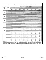
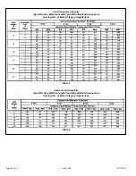
Table 10
Содержание 80G2UH-V
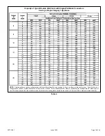
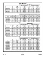
Страница 29: ...507335 01 Page 29 of 44 Issue 1624 ADJUSTING AIRFLOW Table 11 ...
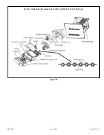
Страница 37: ...507335 01 Page 37 of 44 Issue 1624 Burner Combustion Air Inducer Assembly and Heat Exchanger Removal Figure 38 ...
Страница 41: ...507335 01 Page 41 of 44 Issue 1624 Wiring Diagram Figure 41 ...
Страница 42: ...507335 01 Page 42 of 44 Issue 1624 Typical Field Wiring Diagram Figure 42 ...
Страница 43: ...507335 01 Page 43 of 44 Issue 1624 Start Up Performance Check List UNIT SET UP ...
Страница 44: ...507335 01 Page 44 of 44 Issue 1624 UNIT OPERATION ...