

507335-01
Page 10 of 44
Issue 1624
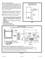
Return Air - Upflow Applications
Return air can be brought in through the bottom or either
side of the furnace installed in an upflow application. If the
furnace is installed on a platform with bottom return, make
an airtight seal between the bottom of the furnace and the
platform to ensure that the furnace operates properly and
safely. The furnace is equipped with a removable bottom
panel to facilitate installation.
Markings are provided on both sides of the furnace cabinet
for installations that require side return air. Cut the furnace
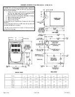
cabinet at the maximum dimensions shown on page 2.
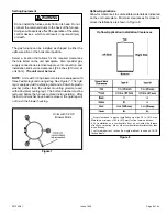
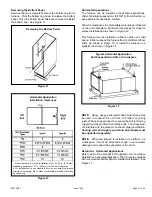
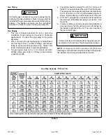
NOTE:
20C and 20D units that require air volumes over
1800 cfm (850 L/s) must have
one of
the following:
1.
Single side return air with transition to accommodate
20
x 25 x 1
in. (508
x 635 x 25
mm) cleanable air filter.
(Required to maintain proper air velocity.)
See
Figure 9.
2.
Single side return air with optional return airbase.
See
Figure 10.
3.
Bottom return air.
4.
Return air from both sides.
5.
Bottom and
one
side return air.
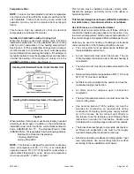
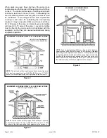
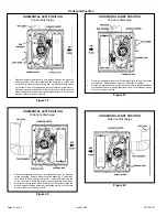
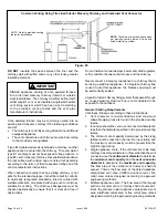
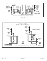
Figure 9
Single Side Return Air
(with transition and filter)
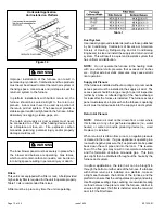
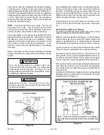
Optional Return Air Base
(Upflow Applications Only - For use with A, B, C and D cabinets))
NOTE:
Optional Side Return Air Filter Kits are not for use with Return Air Base.
1 Both the unit return air opening and the base return air opening must be covered by a single plenum or IAQ cabinet.
Minimum unit side return air opening dimensions for units requiring 1800 cfm or more of air (W x H): 23 x 11 in. (584 x 279 mm).
The opening can be cut as needed to accommodate plenum or IAQ cabinet while maintaining dimensions shown.
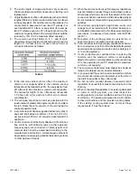
Side return air openings must be cut in the field. There are cutting guides stenciled on the cabinet for the side return air opening.
The size of the opening must not extend beyond the markings on the furnace cabinet.
² To minimize pressure drop, the largest opening height possible (up to 14 inches) is preferred.
Figure 10
Содержание 80G2UH-V
Страница 29: ...507335 01 Page 29 of 44 Issue 1624 ADJUSTING AIRFLOW Table 11 ...
Страница 37: ...507335 01 Page 37 of 44 Issue 1624 Burner Combustion Air Inducer Assembly and Heat Exchanger Removal Figure 38 ...
Страница 41: ...507335 01 Page 41 of 44 Issue 1624 Wiring Diagram Figure 41 ...
Страница 42: ...507335 01 Page 42 of 44 Issue 1624 Typical Field Wiring Diagram Figure 42 ...
Страница 43: ...507335 01 Page 43 of 44 Issue 1624 Start Up Performance Check List UNIT SET UP ...
Страница 44: ...507335 01 Page 44 of 44 Issue 1624 UNIT OPERATION ...