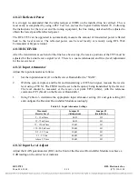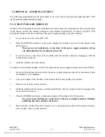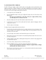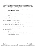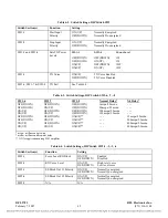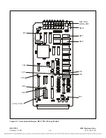
Table 6-2. Switch Settings, DIP Switch SW1
Switch Section(s)
Function
Setting
SW1-1
Start
Input
Polarity
ON (UP)
Normally Energized
OFF(DOWN)
Normally De-energized
SW1-2
Stop
Input
Polarity
ON (UP)
Normally Energized
OFF(DOWN)
Normally De-energized
SW1-3 and SW1-4
Sets TX Power
Levels
SW1-3
SW1-4
Power Level
OFF(DOWN)
OFF(DOWN) 1W
OFF(DOWN)
ON(UP)
3W
ON(UP)
OFF(DOWN) 10W
ON(UP)
ON(UP)
10W
SW1-5
TX Voice
ON(UP)
TX Voice Enabled
OFF(DOWN)
TX Voice Disabled
SW1-6, SW1-7 & SW1-8
TX Fail
See Table 6-3.
Table 6-3. Switch Settings, DIP Switch SW1-6, -7, -8
SW1-6
OFF(DOWN)
OFF(DOWN)
ON(UP)
ON(UP)
OFF(DOWN)
OFF(DOWN)
ON(UP)
ON(UP)
SW1-7
OFF(DOWN)
ON(UP)
OFF(DOWN)
ON(UP)
OFF(DOWN)
ON(UP)
OFF(DOWN)
ON(UP)
SW1-8
OFF(DOWN)
OFF(DOWN)
OFF(DOWN)
OFF(DOWN)
ON(UP)**
ON(UP)**
ON(UP)**
ON(UP)**
Normal Delay*
3mspu/2.5msdo
50mspu/2.5msdo
100mspu/2.5msdo
150mspu/2.5msdo
- - -
- - -
- - -
- - -
X4 Delay*
- - -
- - -
- - -
- - -
12mspu/2.5msdo
200mspu/2.5msdo
400mspu/2.5msdo
600mspu/2.5msdo
* mspu = millisecond pick-up
* msdo = millisecond drop-out delay
** ON for applications using 9505 amplifier
Table 6-4. Switch Settings, DIP Switch SW2-1, -2, -3, -4
Switch Section(s)
Function
Setting
SW2-1
Force Local RX Block
ON(UP)
Enabled
OFF(DOWN) Disabled
SW2-2
RX Voice Level
ON(UP)
High level voice
OFF(DOWN)
Low level voice
SW2-3
SS Block Out #1 Polarity
ON(UP)
Normally energized
OFF(DOWN) Normally
de-energized
SW2-4
SS Block Out #2 Polarity
ON(UP)
Normally energized
OFF(DOWN)
Normally de-energized
SW2-5
N/A
N/A
RFL 9785
RFL Electronics Inc.
February 7, 2007
6-7
(973) 334-3100


